In relation to bonding a sheet material to another material, either a sheet or other structure, I posted the Link recently.
The bonding material used will allow for a precise calculation of the weight being added, as for the success of the adhesion, that will have to be learnt from user experience.
"@ Veleric The Link will show the interface material to be used as the bonding for the Stretch Skin / Honeycomb.
The adhesive film is 150g/m2 prior to the Heat Treatment needed to activate the bonding process.
Maybe, the adhesive film is enough as the stretch skin for a DML Panel?
There is also Carbon Fibre rigid sheet to be used as stretch skin, starting at 0.25mm thickness to be found on the link.
https://www.easycomposites.co.uk/xa120-prepreg-adhesive-film "

Dave,Using this earlier post as inspiration, here's a graph of the wavespeed in my gator board PETTaLS simulation with two different cutoff frequencies (which roughly defines the "corner" where the model becomes primarily nondispersive). Blue line is cutoff=infinity, yellow line is cutoff=20kHz, red line is cutoff=4kHz. I'm sure the "thick plate" model is a better fit, but this might work okay for the time being!
Those wave speed plots certainly do look reasonable. But the question I'm still struggling with is how I might guesstimate a cufoff frequency. My first thought is that it might be better to use a cutoff wave speed instead of a frequency. The reason I suggest that is that while I'm not sure how I would guess at the cutoff frequency, I think I could make a reasonable stab at the limiting wave speed. I think it is reasonable to guess at a limiting wave speed for a sandwich plate using this equation:
where I would approximate G as the appropriate shear modulus of the core material alone, and for density I would use the "apparent density" of the full composite (i.e. its areal density divided by thickness), and use K~1. Obviously it's only a rough approximation, but at least it's not just a wild guess.
Eric
lekha,I would direct those questions to Mark Bosko himself.
No doubt Dr. Bocko would be able to teach us much.
Eric
All those ideas are his, after all. 🙂No doubt Dr. Bocko would be able to teach us much.
Somewhat cheaper from China ...In relation to bonding a sheet material to another material, either a sheet or other structure,
You can also find quite thin alumina (ceramic) sheets there, as well as some honeycomb sheets.
The range of foils from China are able to give a vast range on options for the finished aesthetics of the Panel, if chosen to be used on the exposed side of the Panel.
I am very familiar with Foils on Glass, to the point at one time in my life, I have applied 100's of m2.
These designs for a Foil are not permanent and are quite easy remove, hence there is not a Composite finish between the materials bonded together, there is no need to be destructive to the produced structure when removing this type of Foil.
A Bond that is not a Composite Design, is quite different to the way I understand the Bonds created by the DML Builders used to date in this thread.
The Adhesive Film I have referred to in the Link, will produce a Bond that is to produce a Composite end bond that has the materials only separable if there is a destruction of the produced structure.
The unknown to myself is, how adhered must an added layer be, for the produced panel to be at its optimised to suit the DML design?
I'm very curious about mixing panels now. I have been reluctant to add a x-over, but looking at the response graphs of Xcite XTB40 and XT25 and considering how well DML speakers tend to EQ and blend, splitting up the speaker in individual plates might not be a bad idea after all. I think one could make them blend nicely just using very simple first order filters quite high up, around 4kHz perhaps. Not needing a x-over to cover from 100Hz or so and up, is one of the benefits of DML, but easy blending of multiple sources is another that might outweigh that disadvantage. A 6dB filter on a typical tweeter can be ill advised since it will let through too much low frequencies, but the XT25 should not have a problem, and the XTB40 does handle up to 8kHz quite ok according to Xcites response graphs, so it might sound good with some gentle blending and then some final adjustments of the overall signal with DSP.Thanks Dave.
I second Eric's interest in the effects of adding a spine, as support for exciters, esp the heavier ones, becomes an issue to prevent sag. I've been adopting a system where the exciter is tethered to the panel with a tension strap which has worked ok, but it would be excellent to lay to rest questions regarding the use of spines on the response.
Also, how difficult world it be to incorporate panel splitting? Ie.. Superimpose the results of two panels of independent size, materials and exciters. One may be optimised for bass, and one for mid and high frequencies.
The proposed pricing model also seems fair to me. Good news
Thanks
Eucy
I just thought I finished next revision of my design, but this idea means re-evaluating pretty much everything 🙂 Exciter choice, plate material, dimensions and treatment, suspension, etc, all have to be considered again for ability to reproduce only HF or only mid :\
Compared to using a cluster of 4x XT32, it would reduce the cost of exciters per plate, give better HF response and might mean I'm able to improve power density slightly.
@EarthTonesElectronics
Very nice work on PETTaLS! Seems like just like what I would need now, so quite sure you got a customer here 🙂 Will read up a bit on what you posted so far and give some feedback.
I was just looking over the specs for the Xcite exciters, and noticed this note on the spec sheet:

What does R=2 mean? Hmm, panel aspect ratio? So the panel was 0.39 m x 0.78 m?
Eric
What does R=2 mean? Hmm, panel aspect ratio? So the panel was 0.39 m x 0.78 m?
Eric
Hello Eric,What does R=2 mean? Hmm, panel aspect ratio? So the panel was 0.39 m x 0.78 m?
Yes ratio of 2 is my understanding.
Go back to post #12968 and after when one video from B Zenker about exciter placement was shared.
Christian
I decided to test a different strategy with respect to exciter placement than I have ever tried before. The idea was to position four identical exciters at the 0.33/0.33 locations of a simply supported panel. The exciters would all be driven in-phase with each other. This arrangement would drive the fundamental (1,1) mode very effectively. However, because the 0.33 positions are at nodes of the (1,3), (3,1) and (3,3) modes, none of those modes should be driven. Also, since all (even, even) and (even, odd) modes are all anti-symmetrical wrt one (or both) axis of the panel axes, none of those modes should be driven either. So, the next mode driven above the (1,1) mode would be the (1,5) mode.
The thought was that in the low frequency region, where the modal density is low and the frequency response is lumpy, driving only the fundamental might result in a smoother frequency response in that region.
For this test I used one of my carbon fiber skin/balsa core panels that is mounted in a frame using Poron 92 foam all around the perimeter. This mounting provides edge constraint that is close to "simple" supports and provides high perimeter damping. The exciters were DAEX25VT-4.

I was happily surprised to find that it actually worked quite well. The impedance plot directly below shows a peak at low frequency (27 Hz) corresponding to the magnet resonance of the exciters. The next peak at just over 100 Hz is the panel fundamental. The big gap between the 100 and 600 Hz confirms that no other mode is substantially driven until about 600 Hz, approximately where the (1,5) ought to be, based on my FEA model of the panel. So this result seems to confirm that my basic objective of driving only the 1,1 mode over the lower frequency range was achieved.
The frequency response was pretty good too. About as good or better than anything else I have built. Sounded great on a live track of the Eagles "Hotel California", and Dire Straits "Telegraph Road" and more. I did boost both the bass and treble a bit to flatten the curve, but response is good from about 80 Hz to 16 kHz.
Also shown below are the impulse response and spectrogram plots, both of which are also about as good or better than anything I have built before.
Eric


The thought was that in the low frequency region, where the modal density is low and the frequency response is lumpy, driving only the fundamental might result in a smoother frequency response in that region.
For this test I used one of my carbon fiber skin/balsa core panels that is mounted in a frame using Poron 92 foam all around the perimeter. This mounting provides edge constraint that is close to "simple" supports and provides high perimeter damping. The exciters were DAEX25VT-4.
I was happily surprised to find that it actually worked quite well. The impedance plot directly below shows a peak at low frequency (27 Hz) corresponding to the magnet resonance of the exciters. The next peak at just over 100 Hz is the panel fundamental. The big gap between the 100 and 600 Hz confirms that no other mode is substantially driven until about 600 Hz, approximately where the (1,5) ought to be, based on my FEA model of the panel. So this result seems to confirm that my basic objective of driving only the 1,1 mode over the lower frequency range was achieved.
The frequency response was pretty good too. About as good or better than anything else I have built. Sounded great on a live track of the Eagles "Hotel California", and Dire Straits "Telegraph Road" and more. I did boost both the bass and treble a bit to flatten the curve, but response is good from about 80 Hz to 16 kHz.
Also shown below are the impulse response and spectrogram plots, both of which are also about as good or better than anything I have built before.
Eric
Hi all -
A lot to respond to! @Veleric, your recent experiment is great - if you're interested, this is more or less the idea that I experimented with during my PhD and spent quite a lot of time optimizing. In particular, I wrote about the idea of a "modal crossover network" here, where you send the low frequencies through an exciter array that only actuates the first mode, then the high frequencies through a single exciter positioned well to avoid sharp nodes and antinodes. This technique usually makes for a pretty good sounding loudspeaker, but was very undesirable to companies because more exciters are too expensive! One of my favorite papers that I ever wrote was about solving the inverse problem of minimizing the exciters in an optimized array pattern for a given bandwidth that you want to eliminate modes over (and only excite the lowest mode in). That paper is here. If you can't access the papers just let me know in a DM and I can send them to you (I don't think I'm allowed to post them publicly). I never experimented with this technique on panels with free edges or different boundary conditions - that would be an interesting next step...
The impedance capabilities that you asked me to build into PETTaLS is bringing something up that I need to do more experiments with. It looks like I'm able to predict the panel surface velocity pretty accurately (good enough for government work, at least), as you can see in the pictures below, but the impedance is definitely wonky. It's hard to tell what's going on, but the peaks in the impedance due to the modes are either way higher amplitude or way higher Q than what my model predicts. I can tell that one source of error that I never corrected for is that the lowest mode generally has a low Q relative to other modes due to acoustic loading, and you can see those effects in these graphs. This was for an acrylic panel, which I totally understand nobody uses, but it makes for a good experimental testbench. (blue is PETTaLS, orange is experimental)


I should say to @Eucyblues99 from a few days ago that I understand the impatience - but adding in all of these technical additions take time, and I don't want to release something that I haven't experimentally validated. I've had to derive quite a few equations for these things already! Also, the main effect of adding the spine is that the resonance of the exciter stops affecting the low-frequency cutoff of the speaker, more or less. It also seems to slightly increase the Q of the modes in the simulation, but I need to do more research on that to confirm that it's actually what happens in practice.
Last thing - Eric, I understand more what you're getting at now with the thick plate model. You're interested in solving an inverse problem where you can specify material properties in the software to optimize the sound, then try to find or create a material that has those parameters? That makes sense to me, and I get why the frequency cutoff or wave speed cutoff model is definitely too simple for what you're trying to do. It'll take time to work in a thick plate model (especially because I'm an electrical engineer). Hopefully the wave speed cutoff model for dispersive/nondispersive works okay for v1.0!
Dave
A lot to respond to! @Veleric, your recent experiment is great - if you're interested, this is more or less the idea that I experimented with during my PhD and spent quite a lot of time optimizing. In particular, I wrote about the idea of a "modal crossover network" here, where you send the low frequencies through an exciter array that only actuates the first mode, then the high frequencies through a single exciter positioned well to avoid sharp nodes and antinodes. This technique usually makes for a pretty good sounding loudspeaker, but was very undesirable to companies because more exciters are too expensive! One of my favorite papers that I ever wrote was about solving the inverse problem of minimizing the exciters in an optimized array pattern for a given bandwidth that you want to eliminate modes over (and only excite the lowest mode in). That paper is here. If you can't access the papers just let me know in a DM and I can send them to you (I don't think I'm allowed to post them publicly). I never experimented with this technique on panels with free edges or different boundary conditions - that would be an interesting next step...
The impedance capabilities that you asked me to build into PETTaLS is bringing something up that I need to do more experiments with. It looks like I'm able to predict the panel surface velocity pretty accurately (good enough for government work, at least), as you can see in the pictures below, but the impedance is definitely wonky. It's hard to tell what's going on, but the peaks in the impedance due to the modes are either way higher amplitude or way higher Q than what my model predicts. I can tell that one source of error that I never corrected for is that the lowest mode generally has a low Q relative to other modes due to acoustic loading, and you can see those effects in these graphs. This was for an acrylic panel, which I totally understand nobody uses, but it makes for a good experimental testbench. (blue is PETTaLS, orange is experimental)
I should say to @Eucyblues99 from a few days ago that I understand the impatience - but adding in all of these technical additions take time, and I don't want to release something that I haven't experimentally validated. I've had to derive quite a few equations for these things already! Also, the main effect of adding the spine is that the resonance of the exciter stops affecting the low-frequency cutoff of the speaker, more or less. It also seems to slightly increase the Q of the modes in the simulation, but I need to do more research on that to confirm that it's actually what happens in practice.
Last thing - Eric, I understand more what you're getting at now with the thick plate model. You're interested in solving an inverse problem where you can specify material properties in the software to optimize the sound, then try to find or create a material that has those parameters? That makes sense to me, and I get why the frequency cutoff or wave speed cutoff model is definitely too simple for what you're trying to do. It'll take time to work in a thick plate model (especially because I'm an electrical engineer). Hopefully the wave speed cutoff model for dispersive/nondispersive works okay for v1.0!
Dave
As an engineer, could you explain this phenomenon?... (especially because I'm an electrical engineer).
It is not a long video. In the first part, the flattened coil is at least glued onto a piece of thin membrane, and in the second part, the smaller coil relies solely on the glue to hold it together. But, they both sing!
You must have noticed that the best sound is produced when the middle of that coil is centred in the gap between the neodymium magnets.
For sure, my experiment was inspired by your papers. The single mode DML, haha.this is more or less the idea that I experimented with during my PhD and spent quite a lot of time optimizing.
Exactly.Eric, I understand more what you're getting at now with the thick plate model. You're interested in solving an inverse problem where you can specify material properties in the software to optimize the sound, then try to find or create a material that has those parameters?
Eric
Dave,I can tell that one source of error that I never corrected for is that the lowest mode generally has a low Q relative to other modes due to acoustic loading, and you can see those effects in these graphs.
If I understand correctly, you are talking about the fact that the panel pushing against the adjacent air causes some viscous resistance to the panel's motion, and hence reducing its Q, and that that effect is not included in your model, is that right? And then, are you saying that the lowest frequency is most impacted by this effect? If so, is that due to the relatively higher panel velocity for that mode?
I had always thought maybe the opposite was the case, that is, that the high frequencies were the most "damped" by acoustic loading. I surmised that acoustic "damping" was the reason that the impedance peaks seem to disappear at high frequencies. But I'm sensing now that I was wrong about that. Can you clarify what's actually happening?
Thanks,
Eric
Hi Eric .. Yep..I believe the R factor is the aspect ratio
I was contemplating getting some of these to try, but the costs including postage is not insignificant...
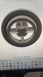
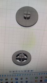
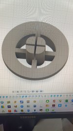
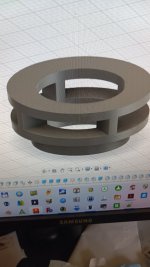
On a different topic, I played around with the so called force concentrator. I printed a test unit with a sealed top and immediately noticed the drum head resonance as it acted like a small diameter diaphragm. I then modified it to an open design as shown in the attached pics...Problem solved. It brings into question the Dayton screw mounts, and does give credence to the cavity resonance argument discussed previously. Perhaps even without the "concentrator", exciter mounts should take the form of a vented extension of the coil ring
The cruciform is for my particular usage
Cheers
Eucy
I was contemplating getting some of these to try, but the costs including postage is not insignificant...
On a different topic, I played around with the so called force concentrator. I printed a test unit with a sealed top and immediately noticed the drum head resonance as it acted like a small diameter diaphragm. I then modified it to an open design as shown in the attached pics...Problem solved. It brings into question the Dayton screw mounts, and does give credence to the cavity resonance argument discussed previously. Perhaps even without the "concentrator", exciter mounts should take the form of a vented extension of the coil ring
The cruciform is for my particular usage
Cheers
Eucy
Attachments
Thanks Daveshould say to @Eucyblues99 from a few days ago that I understand the impatience - but adding in all of these technical additions take time, and I don't want to release something that I haven't experimentally validated. I've had to derive quite a few equations for these things already
I totally understand
Cheers
Eucy
Something like this:Perhaps even without the "concentrator", exciter mounts should take the form of a vented extension of the coil ring
Eucy
Attachments
Hello Eric,The idea was to position four identical exciters at the 0.33/0.33 locations of a simply supported panel. The exciters would all be driven in-phase with each other. This arrangement would drive the fundamental (1,1) mode very effectively. However, because the 0.33 positions are at nodes of the (1,3), (3,1) and (3,3) modes, none of those modes should be driven. Also, since all (even, even) and (even, odd) modes are all anti-symmetrical wrt one (or both) axis of the panel axes, none of those modes should be driven either. So, the next mode driven above the (1,1) mode would be the (1,5) mode.
Could you summarize what leads you to that test and why it gives a such FR? Up to now, the main direction was to use an exciter position that excite as many modes as possible, mainly in for the first mode. Here the contribution of the mode (1,3) and (3,1) are reduced....
The effect of an exciter network in HF was a topic of long exchanges here. Now with the directivity test we have a new tool to have a look to what happens. Would it be possible you make measurements according angles? A 0 to 90° would be very good. As previously, I can extract the plot.
Christian
Hello Dave,I can tell that one source of error that I never corrected for is that the lowest mode generally has a low Q relative to other modes due to acoustic loading,
I think that like Eric, I would like to understand more about that. I have in mind that all the papers that simulate a panel propose to neglect the acoustic load. By the way, I don't have in mind one giving the impedance... If I make a parallel to a model of pistonic loudspeaker, the air is a mass acting in addition to the driver mass. I don't the time right now to check the element of this model...
Christian
Hello Eucy,On a different topic, I played around with the so called force concentrator. I printed a test unit with a sealed top and immediately noticed the drum head resonance as it acted like a small diameter diaphragm. I then modified it to an open design as shown in the attached pics...Problem solved. It brings into question the Dayton screw mounts, and does give credence to the cavity resonance argument discussed previously. Perhaps even without the "concentrator", exciter mounts should take the form of a vented extension of the coil ring
There are 2 topics behind the "concentrator" : one is to create a vented area to avoid the cavity noise. The cavity noise is mainly visible on an FR of the rear side of the panel in the 2...3kHz range. The second is to reduce the diameter of the interface of the exciter to the panel to avoid a loss of HF and the drum effect (resonance of the central area generally in the 10kHz range).
Have you tested your part on a panel?
Which weight is your part?
I ask about the weight because I have always in mind the possible effect on HF of it (and always looking for evidences...).
Christian
- Home
- Loudspeakers
- Full Range
- A Study of DMLs as a Full Range Speaker