Yes, thanks, I wanted confirmation, for me it is important to reduce the weight as much as possible for professional use, at the moment I used a very hard wooden frame, now I want to understand how to make a rear structure if in metal (very complicated) or just do with the same wood for the frame to hold the exciters, I don't know which one exactly to use to minimize vibrations but also to consider the feasibility of the thing, I would like to look for a system that is also decent to present but I certainly cannot afford structures like tectonic. I accept any adviceI don't think it's the thickness, per se, that's important, but rather the stiffness of the frame. .
Depending how you have damped the edges of the panel, the frame might make a greater or lesser difference. There are many variables.
What exactly are you referring to here?now, the foam is tight. Does it need to just barely touch? or how much friction?
Do you mean the exciter to the foam? If so, then the voice coil of the exciter should be adhered to the panel in such away that its resting position is exactly the same as if there was no panel. It must only-just touch.
If you position it tightly by forcing it between the panel and the spine, then you're going to get high distortion and also slam the back of the voice coil into the magnet at bass frequencies.
Why exactly do you want to minimize vibrations?don't know which one exactly to use to minimize vibrations
Im assuming he is talking about the foam within the frame.What exactly are you referring to here?
Do you mean the exciter to the foam? If so, then the voice coil of the exciter should be adhered to the panel in such away that its resting position is exactly the same as if there was no panel. It must only-just touch.
If you position it tightly by forcing it between the panel and the spine, then you're going to get high distortion and also slam the back of the voice coil into the magnet at bass frequencies.
What I understood from the information from Tectonic Pro Audio, that they would "not recommend using the BMR (TEBM65C20F-8), even without the membrane as its designed very differently than the exciters." I was thinking of dismantling a BMR to get at the voice coil to use as the exciter, so I asked Tectonic. It has too much coil excursion, whereas for an exciter, it should be practically nil. It becomes a BMR, only with the membrane on, and without, it is just a voice coil and a magnetic system.Yes, there is a resonance peak on the mbr driver. However it is not present when I remove the diaphragm and use it as an ”exciter”. Yes, I remove the complete diaphragm and connect the voicecoil directly to the diaphragm.
So, did you use the dismantled BMR for a project which needed more pistonic motion? Did you feel that once the membrane off, the voice coil is too elastic, that is, its coil excursion is even more? Once you glued your membrane onto the voice coil, did the excursion become less? What is the diameter of the Tectonic BMR membrane, the one you cut off?
no I meant the spurious vibrations of the structure that holds the exciters, sorry I explained myself badlyWhy exactly do you want to minimize vibrations?
It should be tight as possible.
6watts is good for this small panel size.
Either dead center or 1/2inch off dead center.
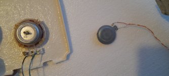
The magnet of the exciter is glued on directly to the spine while the voice coil of the exciter is glued (2 part epoxy adhesive) directly to the foam.
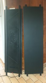
View attachment 1142092
You seem to have accidentally posted a picture of your panels 😱
Is that sound of thunder, the running of feet to the patent office, oh no , its my stomach rumbling, I have not had breakfast yet 🤣
Does this mean you are going to ditch the rug ?
Joking aside, that looks like a solid build.
I must get back to building my EPS panels, and stop this playing around with panel types and implementations.
Steve.

Chdsl.
In the animation you posted they have the two rings inside the coil area, does this exciter modal exist?
I have seen this type of animation before, an exaggerated low frequency tin can effect.
What you really want to see is what is happening in the 10k to 20k area.
Warts and all.
Steve.
In the animation you posted they have the two rings inside the coil area, does this exciter modal exist?
I have seen this type of animation before, an exaggerated low frequency tin can effect.
What you really want to see is what is happening in the 10k to 20k area.
Warts and all.
Steve.
The animation is from the BMR Tectonic markets. It is not an exciter.Chdsl.
In the animation you posted they have the two rings inside the coil area, does this exciter modal exist?
The questions in the post is about what Sandasnickaren had done with a BMR TEBM65C20F-8. I was debating whether to buy such BMRs and take off the membrane, for they are much cheaper and powerful than exciters.
----------------------------------------------------------
Also, I noticed from the link given in your post #9,291, that the Dayton Audio DAEX25FHE-4 sound exciter advertised there is from Billionsound and made with Billionsound Technology (underlined in red in the image).
It so appears that those exciters are from this Chinese technology, only rebranded. Since seeing this, I've been looking for Dayton patents, but I didn't find any yet. If anyone can find such patents, I'd be glad to read them.
This is the patent I found which belongs to Billionsound. It is active until 2032.
Is he back!??🤦♂️🤦♂️Chdsl.
In the animation you posted they have the two rings inside the coil area, does this exciter modal exist?
I have seen this type of animation before, an exaggerated low frequency tin can effect.
What you really want to see is what is happening in the 10k to 20k area.
Warts and all.
Steve.
NO, Please don't encourage him! 🤣
EPS... you serious?I must get back to building my EPS panels, and stop this playing around with panel types and implementations.
Steve.
Audiofrenzy.
As luck would have it, yesterday I glued this ,what I think is a 3watt exciter to a soft low grade 2cm EPS panel that I just had lying around.
I have not a clue where I got the exciter from some years ago, it might have been from a toy or card ?
I am getting a decent volume out of this exciter xoing at 200hz.
I measured it and as expected the hf above 10k drops significantly.
But not bad considering the response plots shown from dayton.
Will cover this panel with pva and see what happens to the hf.
I will probably eventually try this on my flexible ply pane to see how high the frequency will go and if there are any peaks higher up.
Steve.
Attachments

dittoYou seem to have accidentally posted a picture of your panels 😱
Is that sound of thunder, the running of feet to the patent office, oh no , its my stomach rumbling, I have not had breakfast yet 🤣
Does this mean you are going to ditch the rug ?
Joking aside, that looks like a solid build.
PLEASE DON'T !!!!!!!!!!!!!!!!!!!Is he back!??🤦♂️🤦♂️
NO, Please don't encourage him! 🤣
The problem that troubled me was whether I could achieve below 100Hz from any of the available exciters in the market today in the US, UK or the EU, so decided to ask the people concerned, that is, those who market the exciters in the US, UK and the EU, from their tech departments. Most of the replies were like this;
The size of the panel is 540mm x 360mm, 3mm cf-balsa-cf or 3mm, 4mm paper honeycomb, both sides fully prepared, or 3mm pine 3-ply, or 3mm pine-balsa-pine ply. Plywood is not supposed to be prepared according to some people. All these materials is at hand.
That's a diplomatic way of saying that it can't be achieved. So, a sub would be needed to compensate the LF.Achieving an even frequency response below 100Hz is extremely difficult, especially based on the dimensions of your panel, so I would not expect much performance or output in that range.
The size of the panel is 540mm x 360mm, 3mm cf-balsa-cf or 3mm, 4mm paper honeycomb, both sides fully prepared, or 3mm pine 3-ply, or 3mm pine-balsa-pine ply. Plywood is not supposed to be prepared according to some people. All these materials is at hand.
Last edited:
One possibility;
Two exciters, 50mm, 40W, below and a 25mm 20W exciter to be placed at an angle on the top left and right corners accordingly (drawings had been posted earlier).
The second possibility;
Cut the panels in the middle half way on the length, and place a different motor, a la rubanoide, and glue some damping to a back panel and close the back with 2 side "bass-reflex" holes (drawings had been posted earlier). The magnets are on the way from China, most probably will arrive in mid-April.
The third possibility;
Would be a complete different motor, a magnetic system to bring the DM vibrations directly to the front surface. The idea comes from the voice coil itself - the coil becomes an electromagnet when the current passes through it. It also vibrates and sings. No images yet.
The probability is high that this would be the loudspeaker I'd be making, as no one that I know of had done that before. The first and the second "possibilities" had been tried by some, so nothing new.
Im assuming he is talking about the foam within the frame.
this is correct. However, I was about to ask the question Andre answered, as I've got the epoxy job done. what a pain, 2nd time in my life I've used epoxy; happened to have some still.
as for the tightness of the foam within the frame, it's relatively snug, but not evenly so at all contact points. If this is critical, there are several ways to put a screw or dowel or something through to increase tension -- I assume you wouldn't want a screw actually poking into the foam although this would be quick and dirty to try.
Suggest you have a look at birch plywood. It’s predictable, strong , light, stable (moisture and temp variations) and pretty good at handling vibrations.Yes, thanks, I wanted confirmation, for me it is important to reduce the weight as much as possible for professional use, at the moment I used a very hard wooden frame, now I want to understand how to make a rear structure if in metal (very complicated) or just do with the same wood for the frame to hold the exciters, I don't know which one exactly to use to minimize vibrations but also to consider the feasibility of the thing, I would like to look for a system that is also decent to present but I certainly cannot afford structures like tectonic. I accept any advice
Stability is important for the parts that is supposed to hold the Exciters as they need to be kept in the proper place for their function.
Thomas
I think you would have to go for profiled aluminium or steel pipe (the lightweight stuff used in lighting trusses.)... for professional use...
Attachments
- Home
- Loudspeakers
- Full Range
- A Study of DMLs as a Full Range Speaker