Good questions which are puzzling me also.It would be interesting to see estimates of an energy balance of a panel, or any loudspeaker really. What energy is input at each frequency, what part is radiated, what part conducted, what part converted to heat. I would guess that if any scheme to absorb energy is actually working well, the media would heat up noticeably, and it’s characteristics would change within a short time of listening. One early experiment I did with xps was to put perforations along the edges of the sheet (with a soldering iron ☺️) I ended up with several rows of slots in various directions. I remember being surprised how little difference it made. I think that to have an effect, the obstacles need to be of the size of the wavelength you want to impede, and you quickly use up a lot of space. Ideal shape I think would be some sort of repeating, self-similar (fractal) pattern of increasing size (bc high freqs are absorbed first in any case). Hole arrays could fit that description. You also need to fill the holes with an absorber. Silicone won’t work well, it’s too elastic. Butyl mastic goo would be better as Eric mentioned, but I suspect the percentage absorption would be rather disappointing with that too.
Another possibility is to integrate an absorber with the baffle - ie the baffle plate surrounds the panel at the edges instead of terminating the panel at the start of the baffle.
Seems half of the problems of audio are about absorbing unwanted sound energy. I was reading last night about transmission line speakers and how the long tapered cavity is all about absorbing the back wave without causing resonances. I thought why not just make a pipe that passes though the roof of your house a points at the sky. Rain might be an issue though.
I think the ideal objective is to have a material where we have a highly transmissible region with a border that absorbs energy. I agree with your question regarding should we be aiming for more resonance nodes more evenly distributed. One of the problems with DML’s I feel is despite the number of papers published there still isn’t a clear theory of operation. It may be the bending wave and distributed modes are describing two completely different systems rather than two aspects of a single system. It would help development to know.
Me heating, although in principle any damping material will heat up the maximum input from the most powerful exciters is 40 watts which, spread out over a large panel, is not a lot of energy even if all of it it converted to heat so I doubt heating will be a show stopper.
I agree hole size effect will be related to wavelength but I feel, with zero evidence to support my view at the moment, that an array of holes presents a more complex picture. What is the effect of an array of holes with a diameter less than a wavelength but with a combined array presentation front greater than a wavelength? Will this larger array have zero effect? I don’t know the answer to that but my intuition, such that it is, tells me it must have some effect.
For a single plank of material and a single point of excitation they sure are complicated beasts.
Burnt

I usually use weights on small panels that I want to use lower down in frequency.Again on the subject of damping, I think that overall it's a losing strategy for DML technology. If you do ever manage to create perfect edge damping, you will have killed the source of sound below coincidence.
Rather that attempt to absorb a problematic resonance, better to create more resonances - as many as possible, as evenly distributed as possible. Any new resonance 'placed' near another in frequency will (a) distribute energy between the two resonance peaks, lowering each from what it would have been if alone and (b) raise the average SPL near that frequency.
I feel sure I have observed this with the spectrum of my ellipses panel. Minimising opportunities for early reflections back to the exciter, minimising parallel edges, creating a smooth distribution of path lengths, and maximising both surface area and perimeter length produced more resonances and smoother spectrum.
Ideally we would have techniques to damp, shift or eliminate or create particular peaks with specific interventions (weights, damping, holes, ). I have found it very difficult to adjust anything predictably, or get a good handle on what is happening exactly when I eg, add a weight somewhere. I still believe such techniques are possible though.
Or to fill in the gaps in the response below about 300hz.
Although I don't usually bother as I XO at about 300hz anyway.
I watch the response in real time as I move the weights (or my fingers)around the panel.
It is easy to do and can improve the sound ,as long as you don't use too many weights , and not too heavy weights.
I personally do not use damping if I can help it, or need it ?
I prefer my panels to vibrate freely and do their stuff , the lighter the panel, the better.
Steve.
An interesting way of point transfer of sound through a spike using a standard driver as the 'exciter' to a Haddock style (Lineaum style) paper cylinders. Lot of DM activity.
7 years ago.
Hello EricDid a new test yesterday. I put my exciter (DEAX25HFE-4) on the top of my bourbon bottle and played one of my favorites (Dire Straights, Telegraph Road). Fortuitously, the top of the bottle had a nice flat surface of the perfect diameter for the exciter. When the bottle was (nearly) full, the sound wasn't great. Low efficiency and very biased to high frequency. Luckily, the exciter has a little hole, so I was able to pour out the bourbon little by little. By the time the bottle was empty, it sounded great!
I did some REW frequency measurements, but curiously, they were almost identical full and empty. Can't explain. Is anybody willing to verify these results with their own tests?
Eric
View attachment 1120946 View attachment 1120947
Low efficiency and biased to HF fit with my current model (meaning knowledge). Heavy => low efficiency, heavy and stiff => high mechanical impedance => less HF cut off with the coil mass.
No problem in your experiment when you poured out the liquid it goes in the voice coil/spider area?
The FR are the results of several treatments of the raw IR. The FR shows the result of the FFT over a time window. Basically 0.5s if I remember.
Have you had a look to FR with lower or even no smoothing (more peaks in one FR?)?
Have you had a look to the spectrograms that can show what happen over the time?
Christian
Yes you are right. Independently of the damping, as many as possible evenly distributed modes is a target. Let see how to go to design rules that meet this.Again on the subject of damping, I think that overall it's a losing strategy for DML technology. If you do ever manage to create perfect edge damping, you will have killed the source of sound below coincidence.
Rather that attempt to absorb a problematic resonance, better to create more resonances - as many as possible, as evenly distributed as possible. Any new resonance 'placed' near another in frequency will (a) distribute energy between the two resonance peaks, lowering each from what it would have been if alone and (b) raise the average SPL near that frequency.
I feel sure I have observed this with the spectrum of my ellipses panel. Minimising opportunities for early reflections back to the exciter, minimising parallel edges, creating a smooth distribution of path lengths, and maximising both surface area and perimeter length produced more resonances and smoother spectrum.
Ideally we would have techniques to damp, shift or eliminate or create particular peaks with specific interventions (weights, damping, holes, ). I have found it very difficult to adjust anything predictably, or get a good handle on what is happening exactly when I eg, add a weight somewhere. I still believe such techniques are possible though.
Christian
Interesting, why is it automatically assumed that the distributed mode/bending waves must travel only on flat surfaces. Why not on curved surfaces, or wavy surfaces?
Yes . A typical can pictured below and my existing foam material.You mean polyurethane foam?
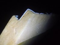
About existing material: At the 1/2" portion I can squeeze with all my might and my finger will indent only about a quarter of the way into the foam and will re-expand to almost flat again. We're talking dense, thus the lower efficiency compared to EPS though I'm not sure how dense EPS gets.
I took these photos at night to capture the glistening that the raw material has. Note the plastic shell of the old cooler. There is no telling how old this cooler is from just the sun damage because down here the sun during summers is brutal. It was a large 4' x2' cooler possibly used on boat by fishermen for their catch which I see a lot. But there are a lot of bars down here and it did have Corona on the side, sooooo?
Anyway, when I compare the materials with a sturdy tap test it seems as the poly and the EPS are very similar with each having a "thud" sound compared to XPS which has a "ding" sound. The poly tone is tighter and seems to carry it's sound slightly after striking it where the EPS just stops. It's sort of a sweet spot between the mellowness of EPS and the higher range of XPS without the "tunnel effect". I think that is why I like this material because it gives off great, smooth, mids and highs as I let the subs do the rest. I'm not going for full range and if I tried, say for some shop speakers, it would be some sort of canvas/tonewood combo.
I'm not sure just how different all the spray foam in cans differ and experimentation would start adding up $, but I'm sure I'll give it a go making at least a couple of panels.
Happy and safe Holidays to all of you and yours !
Attachments

Hello everyone
A long long time ago I mentioned about possibly making a exciter with 3D printing. Now wanting a quick break from my full range driver work, I made this one this week:

It uses my screw in interchangable magnet motor so its easy to swap out most of it from one to the next. Is uses a 20mm VC and design shape is just based upon previous designs. Bl is around 1.9Tm @ 3.2 Ohm and inductance around 0.14mH
I will be getting better materials for the board after taking some time to read through this extensive thread. Just wanted to share that I have gone ahead with producing one as a fun side project.
Terrible video on some old cardboard showing it works in some form is available here:
Paul 🙂
A long long time ago I mentioned about possibly making a exciter with 3D printing. Now wanting a quick break from my full range driver work, I made this one this week:
It uses my screw in interchangable magnet motor so its easy to swap out most of it from one to the next. Is uses a 20mm VC and design shape is just based upon previous designs. Bl is around 1.9Tm @ 3.2 Ohm and inductance around 0.14mH
I will be getting better materials for the board after taking some time to read through this extensive thread. Just wanted to share that I have gone ahead with producing one as a fun side project.
Terrible video on some old cardboard showing it works in some form is available here:
Paul 🙂
Why do you think that is assumed? I’ve never even seen that claim stated. Flat surfaces (plates) are easier to analyse though. General shells are much harder.Interesting, why is it automatically assumed that the distributed mode/bending waves must travel only on flat surfaces. Why not on curved surfaces, or wavy surfaces?
Yes I think this is worth pursuing. It sticks like crazy, so it would be easy to make a composite sandwich panel with faces of glass fibre veil or aluminium foil. It’s on my list of things to try. Just tape the foil to two sheets of ply, wipe with a damp cloth to assist the foam to set, put them together with some spacers around the edges, stick the tube in the middle and spray!Yes . A typical can pictured below and my existing foam material.
About existing material: At the 1/2" portion I can squeeze with all my might and my finger will indent only about a quarter of the way into the foam and will re-expand to almost flat again. We're talking dense, thus the lower efficiency compared to EPS though I'm not sure how dense EPS gets.
I took these photos at night to capture the glistening that the raw material has. Note the plastic shell of the old cooler. There is no telling how old this cooler is from just the sun damage because down here the sun during summers is brutal. It was a large 4' x2' cooler possibly used on boat by fishermen for their catch which I see a lot. But there are a lot of bars down here and it did have Corona on the side, sooooo?
Anyway, when I compare the materials with a sturdy tap test it seems as the poly and the EPS are very similar with each having a "thud" sound compared to XPS which has a "ding" sound. The poly tone is tighter and seems to carry it's sound slightly after striking it where the EPS just stops. It's sort of a sweet spot between the mellowness of EPS and the higher range of XPS without the "tunnel effect". I think that is why I like this material because it gives off great, smooth, mids and highs as I let the subs do the rest. I'm not going for full range and if I tried, say for some shop speakers, it would be some sort of canvas/tonewood combo.
I'm not sure just how different all the spray foam in cans differ and experimentation would start adding up $, but I'm sure I'll give it a go making at least a couple of panels.
Happy and safe Holidays to all of you and yours !
Maybe not. It's actually a lot less than 40 W typically provided from the source, and only a fraction of that is expended in creating sound. But still, we are dealing with small amounts of insulating materials (eg butyl rubber), whose properties are probably quite sensitive to temperature.I doubt heating will be a show stopper.
Agreed!For a single plank of material and a single point of excitation they sure are complicated beasts.
What about this for a simplest-possible exciter idea aiming at directly exciting directional bending waves. Is it worth a try, or doomed to failure? Probably highly non-linear at LF, but idk how much that would matter. Would also have high inductance. Could try first with one bolt only, to see if enough force might be generated to give reasonable efficiency.
The idea is that the neodymium magnets provide repulsive force that prevents contact between the external solenoid, and the panel, so that an oscillating magnetic force (the signal) is added to an overall repulsive force.
1) Wind two solenoids in series on two mild steel machine bolts. Make them opposite magnetic polarity (one head is N, one S). Use enough wire for 4 ohms total. Or maybe make one U-shaped magnet with two heads instead.
2) Glue two small neodymium disc magnets onto the head of each bolt, so that (say) the N poles of each face outward.
3) Glue two more small neodymium disc magnets to the rear of the panel where you wish to excite, again N outward.
4) Mount the bolts through a hole in a rigid member, so the magnet on the bolt head is closely opposed to the one on the panel. Adjust distance by turning bolt.
5) Wire up to amp & listen!
Last edited:
My newest DML panel that I built yesterday. Not completely done but they sound really good IMO.
Hmmmm, I wasn't even thinking composite, just something easy to sand off and leave a raw foam panel to use PVA/water on. Very interesting! thanksYes I think this is worth pursuing. It sticks like crazy, so it would be easy to make a composite sandwich panel with faces of glass fibre veil or aluminium foil. It’s on my list of things to try. Just tape the foil to two sheets of ply, wipe with a damp cloth to assist the foam to set, put them together with some spacers around the edges, stick the tube in the middle and spray!
Diagram to go with previous description.
Use two in opposite polarity for bending wave exciter.

Use two in opposite polarity for bending wave exciter.
I tried this with 2 different bottles - one very heavy single malt bottle and one Jim Beam Black. I just held it to the neck ring. Failed to get excited about it and ditched the bottles (they were already empty) 😊Hello Eric
Low efficiency and biased to HF fit with my current model (meaning knowledge). Heavy => low efficiency, heavy and stiff => high mechanical impedance => less HF cut off with the coil mass.
No problem in your experiment when you poured out the liquid it goes in the voice coil/spider area?
The FR are the results of several treatments of the raw IR. The FR shows the result of the FFT over a time window. Basically 0.5s if I remember.
Have you had a look to FR with lower or even no smoothing (more peaks in one FR?)?
Have you had a look to the spectrograms that can show what happen over the time?
Christian
Probably needed more patience..😒
Eucy
Why do you think that is assumed? I’ve never even seen that claim stated. Flat surfaces (plates) are easier to analyse though. General shells are much harder.
• XPS is manufactured in a continuous extrusion process that produces a homogeneous closed cell cross section.
• EPS is manufactured by expanding spherical beads in a mould, using heat and pressure to fuse the beads together where they touch, leaving open spaces between the beads where they don’t touch.
Although both types are comprised of polystyrene, the two types of manufacturing processes produce finished products with very different performance properties. Of the two types, EPS absorbs more water in laboratory tests and in application resulting in reduced performance (as an insulating material in construction).
Using EPS for the purpose of a DML panel, adding diluted PVA to its surface would only block the nearest empty spaces of the surface. Even, if you paint all the 6 surfaces (2 flat and 4 edges) you'd still have empty spaces within the EPS sheet. Inside the EPS sheet, the spherical polystyrene beads are suspended in air, holding each other by surface tension.
XPS also absorbs water in time, even though its surface looks monolithic, that is, there is air within the XPS sheet. There's a never-ending fight between the EPS and XPS manufacturers in this area. In colder countries, the water consumption by any insulating material is a problem due frost and thaw.
Both EPS and XPS are also very good heat and sound insulators, but EPS is better at it than XPS, especially because of the amount of air trapped in it, that is amount of so-called empty spaces. All foam material (polystyrene, PIR, phenolic, etc) has air trapped in them, some of them has all 6 surfaces blocked as they are extruded.
--------------------------
1) Why there is a tunnel effect in EPS, depending on the thickness of the sheet?
Sound goes everywhere from the exciter. It may travel along the surface, bumping from one polystyrene bead, or going through it, to another. It may go across the EPS sheet in all directions, going through the beads, and then through the 'empty' space into the next bead, and/or bumping of the surface of the bead. Sound (waves) can come out of any place from the other side of the panel, or even from the edges. So, we can assume that thinner the EPS sheet, better the sound. But, very thin (1mm or even less) would simply crack. (I've seen very thin EPS sheets at the factory.)
2) The pebble in pond effect, do the waves really return?
Why should they? EPS (or XPS) is not a liquid. The liquids need a container. Waves hit the bank and return in a pond. The EPS (or XPS) sheet edge is not a barrier. It is open to the air. The sound waves would simply move out from the higher density material (EPS, XPS) to air (low density). They'd go out from the shortest edge quicker than from the longest edge. (The few commercial producers of flat panel speaker available atm in the world, such as Amina Sound, Tectonic etc block the edges with damping material. Amina Sound actually plaster their flat speakers in walls, not very worried about plaster cracking.)
3) Why the edge fixed exciter at the centre gives much clearer and fuller sound from a flat panel? Why glass gives a better sound than EPS or XPS this way?
My piano tuner friend says that the sound moves out like a balloon, mostly forward, depending how the source of the sound is directed. (He is a piano player and a music teacher.) So, the sound balloons off much faster in the high-density glass, and then passes out to the low-density air. Only, it happens so fast for our ears to catch the difference. Glass is much more homogeneous than EPS.
4) Why the curved flat surface, paper in this case, gives out even more clear and full sound than the same paper kept straight with edge transfer of sound? Telefunken Arcophon from 1926 and Paul Haddock's patents from 1990 to 1998.
A piezoelectric driver (20) is the sound source. Flat upturned triangle (18) is the bridge. The curved paper membranes (26) are the DML panels. The membranes are fixed and damped along the perimeter, half of which is practically flat. Of course, this is just a patent, probably the speaker had not been made after the patent was issued, but Telefunken had sold Arcophon speakers with the same idea from 1926-1932. The point transfer of the sound vibrations/waves to an edge of two curved flat panels, in this case paper. In this patent, the perforated edge of the bridge transfers the energy/waves/vibrations to a thin strip at the edge of the two DML panels. Why it gives clearer, fuller sound is not yet answered.
Joppe is experimenting with 4 neodymium magnets 5 years ago.What about this for a simplest-possible exciter idea aiming at directly exciting directional bending waves. Is it worth a try, or doomed to failure? Probably highly non-linear at LF, but idk how much that would matter. Would also have high inductance. Could try first with one bolt only, to see if enough force might be generated to give reasonable efficiency.
The idea is that the neodymium magnets provide repulsive force that prevents contact between the external solenoid, and the panel, so that an oscillating magnetic force (the signal) is added to an overall repulsive force.
1) Wind two solenoids in series on two mild steel machine bolts. Make them opposite magnetic polarity (one head is N, one S). Use enough wire for 4 ohms total. Or maybe make one U-shaped magnet with two heads instead.
2) Glue two small neodymium disc magnets onto the head of each bolt, so that (say) the N poles of each face outward.
3) Glue two more small neodymium disc magnets to the rear of the panel where you wish to excite, again N outward.
4) Mount the bolts through a hole in a rigid member, so the magnet on the bolt head is closely opposed to the one on the panel. Adjust distance by turning bolt.
5) Wire up to amp & listen!
The flat (printed) voice coil is pasted between the two pieces of paper, which are also pasted to each other. The elastic string is to bring back the voice coil from jumping off and keeping it centred between the magnets.
Last edited:
The two panels are somewhat separated from each other. There's a thin strip (paper, aluminium) pasted on the edges of the two panels vertically in the middle (1.33 mins into the video). That is, most probably to get the high frequencies.
- Home
- Loudspeakers
- Full Range
- A Study of DMLs as a Full Range Speaker