EPS plate (neopor) ordering
I just got the information from dekokopf.com they have opened delivery to France (not tested yet). For other (EU?) countries to be checked. Ask them by the contact form.
Christian
PS : I found also this source Zadawerk. The information about the weight give 30kg/m3 (neopor is 25kg/m3 if I remember)... if it is a way to find EPS of the desired quality?
Last edited:
I also think place the ply at center is better. It get a more even mounting force from the fabric around. If place it for example near top left, the ply will be more flapping at its lower right.My panels are approximately 40x30cm , these are the only size I have used, I bought 4 of them in a pack very cheaply, for testing.
I use the exciters in the centre to ballance the panel for pistonic motion in the low frequencies.
I have not noticed anything bad sounding or measurement wise using this position on a ply canvas panel, the canvas and glue damps the panel well.
This also reduces the amount of free flapping of large areas of uncontrollable canvas.
Hkguy6 is correct in saying the canvas sounds like a damped ply.
You can use the canvas only ,without the ply , but the roll off is much higher above 300hz.
Which is good as it keeps the damaging low frequencies away from the canvas.
On my other panels , I use the nxt 4/9 x 3/7 positions which keeps the exciters in a more central position, similar to tectonic speakers ,and supposedly excites a good set of modes ?
But I just prefer the central position of the nxt positions.
But the choice is yours.
The panel in my photo has a lot of the canvas cut away and the canvas is used more as a material surround at the edges.
This increases power handling in the LF without canvas flap and wobble.
Try not to use too thick and rigid a ply panel.
This should also help efficiency.
Even better use an old crate ply (whatever it is) 😀
Steve.
However how much it affact the sound that I'm not sure.
Hi hkguy6I also think place the ply at center is better. It get a more even mounting force from the fabric around. If place it for example near top left, the ply will be more flapping at its lower right.
However how much it affact the sound that I'm not sure.
As written in previous posts, I built a pair of canvas panel and I am quite happy with them. I prefer my plywood one. The canvas are really easy to make.

Christian,Hello Eric
I have also those papers. I found in something probably missing in my previous evaluation of the wave speed : the limitation by the shear speed....
Is there something you would push in front front your re-reading?
Christian
Good question! Like you, the limitation on the wave speed due to the shear modulus caught my attention. It is making me wonder if that is the reason I am not seeing evidence of the coincidence frequency (such as beaming at wide angles) where it "should be". Maybe (due to the shear modulus limitation) some of the panels I'm testing never actually reach coincidence.
But another interesting point is illustrated in Figure 9 of the second tutorial. In my simple (and wrong) mental model, the fall off of radiated power above a particular modes natural frequency occurs as sharply as the rise before it. And while that seems roughly true very close to the natural frequency, it's wrong well above the natural frequency, where the contribution of each mode falls to non-zero plateau. And while the figure stops as only 200 Hz, it seems to suggest that the 1,1 mode is providing a huge portion of the radiated power far, far above the fundamental (1,1) natural frequency.
Eric
t would be 3 for both of us Christian?Your are right Eric : "one hour".
Thank you for the calculation, it is an order of magnitude I didn't have in mind. 50cm in 10ms at 100Hz it is rather slow compare to what we are use to see... it is even one period. By the way the panel is large (120x45cm).
Roughly estimated, the delay for 50cm @10kHz seems 600µs. Knowing it is poplar 3mm to be checked if it is consistent with the basic formulas.
Christian
And density is 400 to 450
Eucy
Not much change Eucy,t would be 3 for both of us Christian?
And density is 400 to 450
Eucy
If I use t=3, rho=425 and E =5 GPa (my guess), I get 11.2 ms for 50 cm at 100 Hz and 1.2 ms at 10,000 Hz. Feel free to check my math!
This is using the formula for wave speed.
where:
But...I have to admit to some uncertainty about whether or not this equation applies for all plate boundary conditions. The reason I say this is the following: Consider for example a simply supported rectangular (but NOT square) plate. The wavelengths in the long and short dimension of the fundamental frequency are obviously different from each other, since both the length and the width of the plate constitute are half of a wavelength, while the frequency is the same for both (i.e. the fundamental). Then, since speed =wavelength x frequency, it seems that the speed of the wave must be different in the two directions. But the speed equation above only has one answer, not two! So either this equation doesn't apply to simply supported plates, or I'm missing something.....but what?
Eric
Then there's the effect of significant anisotropy EricNot much change Eucy,
If I use t=3, rho=425 and E =5 GPa (my guess), I get 11.2 ms for 50 cm at 100 Hz and 1.2 ms at 10,000 Hz. Feel free to check my math!
This is using the formula for wave speed.
View attachment 1093038
where:
View attachment 1093039
But...I have to admit to some uncertainty about whether or not this equation applies for all plate boundary conditions. The reason I say this is the following: Consider for example a simply supported rectangular (but NOT square) plate. The wavelengths in the long and short dimension of the fundamental frequency are obviously different from each other, since both the length and the width of the plate constitute are half of a wavelength, while the frequency is the same for both (i.e. the fundamental). Then, since speed =wavelength x frequency, it seems that the speed of the wave must be different in the two directions. But the speed equation above only has one answer, not two! So either this equation doesn't apply to simply supported plates, or I'm missing something.....but what?
Eric
Eucy
Hi Steve,These are the other 2 types of canvas panels tested so far.
The panel on the right in the two photos is the canvas only panel with home made dome , now concave, oops.
This is to minimise exciter noises.
The one on the left used an ordinary 6x4inch 3mm ply ,but glued to the front ,to try and get a more exciting sound.
I would now use a much larger crate ply panel for this last panel , the crate ply is much more exciting, similar to the EPS, but not quite as much.
Steve.
Does having they ply on the back of the canvas or on the front of the canvas (and exciter directly on the canvas ) does it have any difference in outcome?
So we only need to apply PVA glue on ply to attach to canvas and double side tape to attach exciter. Do we need to put PVA 50% solution on the canvas also or its just plain canvas?
As my experience, the ply on canvas front or back have no sound different. Just aesthetic.Hi Steve,
Does having they ply on the back of the canvas or on the front of the canvas (and exciter directly on the canvas ) does it have any difference in outcome?
So we only need to apply PVA glue on ply to attach to canvas and double side tape to attach exciter. Do we need to put PVA 50% solution on the canvas also or its just plain canvas?
But the exciter facing you or not it does has sound different. As Steve said, sound more exciting. However your exciter has to be noise free or you will hear the noise more clearly if it facing you.
If not with spine. Yes it easy to make.Hi hkguy6
As written in previous posts, I built a pair of canvas panel and I am quite happy with them. I prefer my plywood one. The canvas are really easy to make.
I'm still can't build a spine with the exciter perfectly horizonital and zero pressure against the ply. So I give up the spine.
I just think maybe I'm too serious on this. A little slant and pressure may not affact the sound. But spine system must be difficult to change exciter this's sure.
Hkguy6.I just made a recording of the 2ply aluminium sheet while moving the microphone around the room.
I was then going to cut the panel down another size to match the size of the card panel.
But while I was measuring, I noticed the slight peak at about 5k.
I was a little suspicious of what this was, so turned the panel around.
As you can see in the third picture of the reverse frequency response, the dips either side of the 5k peak.
It does not sound too bad in my room , but if up against a reflective wall this could be a problem.
Also I added some weights to the edges , which improved the output in the 90 hz to 200hz area.
This aloud me to turn the volume up a lot higher, although the exciter is now getting hot 🔥 .
This aluminium panel might actually sound better with some sort of frame or damping?
It does wobble and flex a lot, and when holding the sides the sound does not alter too much higher up in frequency range.
So I am going to play around with this one for a little longer and see what happens.
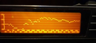
Pic 1 with smaller 12 x7 inch card panel.
Pic 2.
Frequency response of aluminium panel at 1m.
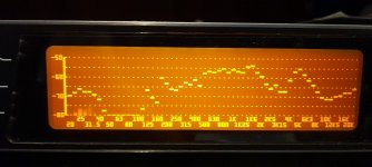
Pic 3.
Response form exciter side of panel same microphone position.
Pic 4.
Panel With the small weights attached.
Steve.
In picture 3 in this post you can see what the affect the exciter has on the frequency response from the rear.
The direct sound from the back surface of the panel is nice but the exciter blocks the HF and causes phase problems.
If you can live with this , then it will be fine ?
Steve.
How close you measure this phase problem? And which range of HF blocked? Forget me I don't know how to read your graph.Hkguy6.
In picture 3 in this post you can see what the affect the exciter has on the frequency response from the rear.
The direct sound from the back surface of the panel is nice but the exciter blocks the HF and causes phase problems.
If you can live with this , then it will be fine ?
Steve.
From about 1M far I don't hear HF lost or phase peoblem when exciter facing me. Oppositely the whole sounding more clear.
I just guess, the exciter itself also provide a level of HF by it's own body. Such as when you hold a exciter on hands to play music it sounds like a tweeter especially the one with vents. Do you find this phase problem on all models of your exciter?
And as you said, when the exciter facing you, means the panel material which side direct accept the virbation also facing you. Imagine if a 10CM thick EPS panel. The direct side should be more clear without the 10CM travel. (sorry for my English. I tried my best...)
I can't remember whether I mentioned this in the past or not, but I coated the panel in a 50x50 mix to start with ,if I remember correctly, then when dry use neat PVA to glue on the panel.Hi Steve,
Does having they ply on the back of the canvas or on the front of the canvas (and exciter directly on the canvas ) does it have any difference in outcome?
So we only need to apply PVA glue on ply to attach to canvas and double side tape to attach exciter. Do we need to put PVA 50% solution on the canvas also or its just plain canvas?
This was to stop the canvas from soaking away (absorbing)the glue, which made a poor bond.
I use pva to glue on my exciters directly to the ply.
The idea was not to have the sound go through the canvas,or a sticky exciter ring, which I believe softens the sound a little.
In the end I preferred the sound and performance of the larger springy crate ply in my photo, so never followed up on this.
You also might want a picture on the front?
The choice is yours.
Steve.
EricChristian,
Good question! Like you, the limitation on the wave speed due to the shear modulus caught my attention. It is making me wonder if that is the reason I am not seeing evidence of the coincidence frequency (such as beaming at wide angles) where it "should be". Maybe (due to the shear modulus limitation) some of the panels I'm testing never actually reach coincidence.
But another interesting point is illustrated in Figure 9 of the second tutorial. In my simple (and wrong) mental model, the fall off of radiated power above a particular modes natural frequency occurs as sharply as the rise before it. And while that seems roughly true very close to the natural frequency, it's wrong well above the natural frequency, where the contribution of each mode falls to non-zero plateau. And while the figure stops as only 200 Hz, it seems to suggest that the 1,1 mode is providing a huge portion of the radiated power far, far above the fundamental (1,1) natural frequency.
Eric
View attachment 1092999
At the moment i don't understand the concept behind this graph : some math trick seems used to "insulate" the radiated power of one mode. I say math trick because I don't understand that from a practical point of view, or let say it doesn't with my internal model.
The plateau is 1/100 of the peaks (vertical axis is almost log) so I guess not a big contribution compare to other peaks/modes.
Christian
In a first step, my canvas panels were without spine. Very easy to build as it is cutting a piece of plywood and gluing. In a second time, I added a spine in the same way as Steve's pictures just before. The key point is to find some piece of wood with the right thickness to avoid any extra force on the exciter. No problem of orientation if the sides of those pieces are parallel. You can use several pieces of different thickness to get the right height. Depending of the frame, the wedge(s) is (are) between the exciter and the spine or the spine and the frame. In my experience, making a panel in a frame with a suspension and a spine is more difficult.If not with spine. Yes it easy to make.
I'm still can't build a spine with the exciter perfectly horizonital and zero pressure against the ply. So I give up the spine.
I just think maybe I'm too serious on this. A little slant and pressure may not affact the sound. But spine system must be difficult to change exciter this's sure.
Yes I have a very clear idea actually.hilbren,
Do you have an idea of what you plan to look for with the accelerometers?
I suspect that a microphone placed very close to the panel surface might give similar information as an accelerometer.
Eric
1. Is to measure the speed of the sound per frequency
2. The decay of each frequency per distance
I want to measure this like linkwitz sometimes measures, short burst of a couple of waves. This way i hope to get values without them being affected by reflections. The difference with a mic is that a vibrating panel does not always makes a sound and a panel standing still does not mean there is no sound at that specific location. Form experience i know a accelerometer gives a cleaner image of what is really happening.
Christian/Homeswing/Hilbren???
it looks like there's a cross-over (with group delay) involved at the 150Hz mark, or standing waves at 80hz via a subwoofer.... What's going on there??
Hi Andre
No crossover, no sub... This is my plywood panel playing full range with the mic being about 5mm from the surface (so very close).1st is at the exciter axis, 2nd is a point in the middle of the width, 40cm below the exciter in vertical. The idea behind those measurements is to see if the mic collects the panel behavior just in front of it, to try to evaluate the wave speed into the panel, the absorption, and the reflected waves. So nothing like a standard measurement like we see more usually around 1m. Nevertheless, I am surprised too. At this point nothing says this measurement makes sense. The purpose, as I am interested also in seeing how the panel behaves, was to share an example of close mic measurement as Eric proposed in a post just before.
Christian
Hi Christian and Andre
I don't know for sure but i going to try to explain. First we separate the different effects we see in the plot:
a. the dip @ 80 Hz @ exciter position VS. the peak @ 80 Hz @ 40 cm away from the exciter
I think this is one of the first modes of the panel, this lowers the acoustic impedance at the exiter position, this is why the output above the exiter is lower.
b. Group delay is not constant (in the 40 cm measurement, the first peak 300 Hz shows ~2 ms delay at 2k-3k this delays decreases to 1 ms)
I think this can be explained by the change of speed of sound for each freq. Like in the paper i mentioned earlier. It's actually very nice to see this in your measurement. I'd like to try to do the same measurement for the material i got here.
I calculated some values, just for fun:
0,4/13e-3=30 m/s @ 100 Hz
0,4/1,5e-3=266 m/s @ 300 Hz
0,4/1,4e-3=285 m/s @ 600 Hz
0,4/1e-3=400 m/sec @ 1 khz
0,4/0,7e-3=571 m/s @ 2 khz
0,4/0,6e-3=666 m/s @ 4 khz
These values are very closely related to the 'Frequency dependent bending wave speeds' you can find on google.
c. Some delays seem almost constant (in the 40 cm measurement, @ 1 khz and 8 ms the delay seems constant unit about 3 khz)
A simple explanation could be so simple as the microphone pics up the sound trough the air, because te speed trough the panel is much higher you first see the effect of situation described in b, then you see the speed of the air, probably a reflection from something 1,2 meters away from your setup. the ground or the ceiling maybe?
While i am waiting for my accelerometers and optic sensors to arrive i made a test setup where one side of the panel is fixed while the exiter is fixed at a position where the panel itself if working as a transmissionline lowering the resonant frequency of the whole system and increasing the bass response, I've got a good feeling this is going to work..
Hello HibrenYes I have a very clear idea actually.
1. Is to measure the speed of the sound per frequency
2. The decay of each frequency per distance
I want to measure this like linkwitz sometimes measures, short burst of a couple of waves. This way i hope to get values without them being affected by reflections. The difference with a mic is that a vibrating panel does not always makes a sound and a panel standing still does not mean there is no sound at that specific location. Form experience i know a accelerometer gives a cleaner image of what is really happening.
Hi Christian and Andre
I don't know for sure but i going to try to explain. First we separate the different effects we see in the plot:
a. the dip @ 80 Hz @ exciter position VS. the peak @ 80 Hz @ 40 cm away from the exciter
I think this is one of the first modes of the panel, this lowers the acoustic impedance at the exiter position, this is why the output above the exiter is lower.
b. Group delay is not constant (in the 40 cm measurement, the first peak 300 Hz shows ~2 ms delay at 2k-3k this delays decreases to 1 ms)
I think this can be explained by the change of speed of sound for each freq. Like in the paper i mentioned earlier. It's actually very nice to see this in your measurement. I'd like to try to do the same measurement for the material i got here.
I calculated some values, just for fun:
0,4/13e-3=30 m/s @ 100 Hz
0,4/1,5e-3=266 m/s @ 300 Hz
0,4/1,4e-3=285 m/s @ 600 Hz
0,4/1e-3=400 m/sec @ 1 khz
0,4/0,7e-3=571 m/s @ 2 khz
0,4/0,6e-3=666 m/s @ 4 khz
These values are very closely related to the 'Frequency dependent bending wave speeds' you can find on google.
c. Some delays seem almost constant (in the 40 cm measurement, @ 1 khz and 8 ms the delay seems constant unit about 3 khz)
A simple explanation could be so simple as the microphone pics up the sound trough the air, because te speed trough the panel is much higher you first see the effect of situation described in b, then you see the speed of the air, probably a reflection from something 1,2 meters away from your setup. the ground or the ceiling maybe?
While i am waiting for my accelerometers and optic sensors to arrive i made a test setup where one side of the panel is fixed while the exiter is fixed at a position where the panel itself if working as a transmissionline lowering the resonant frequency of the whole system and increasing the bass response, I've got a good feeling this is going to work..
Happy to see you have fully understood my intentions!
I don't have the time right now (too late, working day tomorrow...) to go in the details of your post.
I just made a graph from the speeds you estimated, the shape seems as expected but trying to extract some D/µ doesn't work at the moment. Probably something wrong for this evening (too late, too tired?).
Looking back to the speeds you evaluate, they are above the sound speed in the air a little bit before 1kHz so the coincidence frequency evaluation is something like 800Hz which unexpectedly low.
An other remark for now is this is my second tentative with this kind of set up. As you noticed, the front of the first wave seems visible, but where are the reflections?
To be continued...
Agree with you that the mic is probably not the best sensor as it collects other information... but it is available in my basic audio DIYer toolkit.
For brainstorming : does a phono cartridge make sense as a speed sensor? Drawback is the little weight to apply.
Christian
And the effect of the differences in long and cross grain velocity, and the differences in the percentage of long and cross grain material in 3 ply vs 5 ply etc.Then there's the effect of significant anisotropy Eric
Eucy
All in all a very complex set of circumstances.
Eucy
I just made these two measurements of my Ali panel at 60cm, but it is the same from 3m.How close you measure this phase problem? And which range of HF blocked? Forget me I don't know how to read your graph.
From about 1M far I don't hear HF lost or phase peoblem when exciter facing me. Oppositely the whole sounding more clear.
I just guess, the exciter itself also provide a level of HF by it's own body. Such as when you hold a exciter on hands to play music it sounds like a tweeter especially the one with vents. Do you find this phase problem on all models of your exciter?
And as you said, when the exciter facing you, means the panel material which side direct accept the virbation also facing you. Imagine if a 10CM thick EPS panel. The direct side should be more clear without the 10CM travel. (sorry for my English. I tried my best...)
Pic 1.
From the front.
pic 2.
from the back.
This panel suffers quite badly from the rear, not all panel will be as bad.
I did I believe, make a recording not so long ago of the noise produced from the back and front of some panels ?
It is a little difficult to separate the noises, cavity, coil area, and exciter suspension , plus the hole in the magnet.
I can minimise the first two but not the suspension and exciter vibrating in sympathy with the coil and panel.
This is why I would love to try a powerful piezoelectric thin film an the front of a panel.
You could drive the front surface without a large magnet and suspension in the way.
I agree that the main driving surface at the back of the panel sounds much better than the front secondary driving surface.
But the exciter itself is the main problem, which I can only try and minimise.
Steve.
Attachments
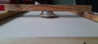
Maybe a pecture will show how easy it is really.In a first step, my canvas panels were without spine. Very easy to build as it is cutting a piece of plywood and gluing. In a second time, I added a spine in the same way as Steve's pictures just before. The key point is to find some piece of wood with the right thickness to avoid any extra force on the exciter. No problem of orientation if the sides of those pieces are parallel. You can use several pieces of different thickness to get the right height. Depending of the frame, the wedge(s) is (are) between the exciter and the spine or the spine and the frame. In my experience, making a panel in a frame with a suspension and a spine is more difficult.
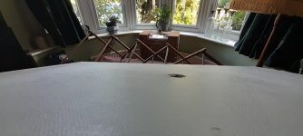
This is a picture of my canvas only panel which has to have a back bracing as the canvas cannot support the exciter.
The method is the same as with a ply panel attached.
I just lay the panel down onto a flat surface and glue the exciter into position.
I place the wood bracing on top of the exciter, and find odd pieces of wood to fill the gaps between frame and bracing.
I found it handy to turn the wood over a few times as a slight bow in the wood can make a big difference and help line things up.
If you have a gap , you could always fill this with silicone or pva or a harder filler.
Or you could do this at the sides where the frame and bracing meet , but I would probably have the bracing going down the panel to stop sagging if silicone was used.
There is a little bit of play( forward and backwards) in the canvas, which is handy ,as this does not put any strain on the coil , and allows the coil to move freely.
You should not be able to see an imprint of the coil or ply panel on the front of the canvas, it should look flat.
As in the photos
Steve.
Attachments
- Home
- Loudspeakers
- Full Range
- A Study of DMLs as a Full Range Speaker