Hello Eric,Christian,
I submit (for now!) that the fact that the response of the mic in our tap tests:
https://www.diyaudio.com/community/...r-dml-design-and-analysis.383567/post-6954047
suggests that the mic is indeed quite selectively showing what is exactly in front of it.
Using the mic as if it is an accelerometer, I can often identify the frequencies and "identities" (i,e: m,n) of the first 10 to 15 natural frequencies of any panel.
What is it in your results that suggests that the mic is not selective enough? What are your expectations, and how were they not met?
Eric
As I had one our "free" for that, my first intention was to test if a set up with the iMM6 with a loopback as a timing reference can work. Seems yes, the delays from one point to other ones are clearly visible. As it uses much more standard components or software than my previous set up it is nice. I have the ambition to write a short paper explaining the set up (a schematics is even enough probably).
As mentioned it is "raw" data meaning I haven't really thought about the result so much... The difference with a tap test is that here the time dimension is added. The spectrogram shows when things occur according to the filter bandwidth selected.
The strange point (unexpected? not explained?) is what Andre also saw : maximum of the frequencies below 250Hz jump suddenly to more than 10ms. So is it an effect of the modes, some wave traveling in the panel, bouncing and coming back? is it some external effect, from the mic, from the surroundings?
Here are two good articles. I may have posted these before but some of you may not have seen them. I just re-read them myself and found some things I did not recall. They are not specifically about DML speakers, but are clearly relevant.
Eric
https://www.researchgate.net/public...tics_Tutorial-Part_1_Vibrations_in_Structures
https://www.researchgate.net/public...s_Tutorial-Part_2_Sound-Structure_Interaction
Eric
https://www.researchgate.net/public...tics_Tutorial-Part_1_Vibrations_in_Structures
https://www.researchgate.net/public...s_Tutorial-Part_2_Sound-Structure_Interaction
Haha, it took me a while to figure out but I think you meant to say you had one "hour" free, rather than one "our"! Glad to see you are making good use of your "ours"! I know I make a lot of typos myself so don't feel bad....I was just glad I figured it out! (I think).Hello Eric,
As I had one our "free" for that, my first intention was to test if a set up with the iMM6 with a loopback as a timing reference can work. Seems yes, the delays from one point to other ones are clearly visible.
Anyway, I'm not sure if it's helpful, or even if I did the calculations correctly, but I just did some quick estimates of the speed of bending waves in a typical plywood panel (E=7 GPa, t=4 mm, rho=600 kg/m3), just to give me some perspective. For such a panel I calculated it to be about 50 m/s for a 100 Hz wave and 500 m/s for a 10,000 Hz wave. To traverse 50 cm, then, the 100 Hz wave should take about 10 ms, and the 10,000 Hz wave about 1 ms.
Eric
yes i agree , they make great full range near field monitors.Yes, that is true - I wanted to say that even without any EQ at the moment (which is for sure necessary with my build) and running full range on low levels, the sound is very enjoyable. Especially stringed instruments, percussions and vocals sound really life like. I am used to hearing this from my huge 4 way horn stack or unity/synergy builds with planar HF, but the area/volume occupied by speakers is incomparable and also I need to sit a bit further back.
The panels work surprisingly well as near field speakers on my desk.
but they can drive full range in the room too as long as you dont expact ac/dc at disco levels .
this is a small clip of the same music as my around room rec.
this is one panel only in mono ,the mic rolls off the low end a little , but is strong down to 40hz.
steve.
Attachments

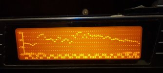
This picture shows the room response of this panel actually playing the music on peak hold at 3m into the room.
The vocals , drum and violin are mainly in the 500hz to 1k hence the raised response in this area, so don't panic😱
Ignore anything below 40 hz as the response of this panel with my exciter drops off like a brick below this.
Obviously 2 combined panels will have more low end power.
Steve.
The vocals , drum and violin are mainly in the 500hz to 1k hence the raised response in this area, so don't panic😱
Ignore anything below 40 hz as the response of this panel with my exciter drops off like a brick below this.
Obviously 2 combined panels will have more low end power.
Steve.
Attachments
When I used to build 7ft panels it was easy to hear these frequencies slowly dying away. when the music was paused .Hello Eric,
As I had one our "free" for that, my first intention was to test if a set up with the iMM6 with a loopback as a timing reference can work. Seems yes, the delays from one point to other ones are clearly visible. As it uses much more standard components or software than my previous set up it is nice. I have the ambition to write a short paper explaining the set up (a schematics is even enough probably).
As mentioned it is "raw" data meaning I haven't really thought about the result so much... The difference with a tap test is that here the time dimension is added. The spectrogram shows when things occur according to the filter bandwidth selected.
The strange point (unexpected? not explained?) is what Andre also saw : maximum of the frequencies below 250Hz jump suddenly to more than 10ms. So is it an effect of the modes, some wave traveling in the panel, bouncing and coming back? is it some external effect, from the mic, from the surroundings?
With smaller panels I can't hear this problem.
There is no way a large panel is going to instantly stop vibrating when the exciter stops.
And if it did , dml would be none existent.
The best you could achieve would be a bendingwave speaker, the smaller the better.
Steve.
Sorry Steve that was my typo. The size should be in CM instead of inch.Hkguy6.
WOW, I thought that pelanj panels might be too big 😃.
It would be interesting to see some measurements and maybe a recording.
My main worry would be the panel flapping especially at higher volumes with such large uncontrolled areas .
Have you tried the smaller panels similar to mine and jaxboy?
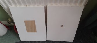
You will still get good LF down to 40hz if using larger ply panels similar to my picture below.
Although for serious listening I would XO above 100hz.
Pva was used to glue on the exciter and 3mm ply that is all that is needed for good results.
Water can be used to shrink the canvas if necessary.
Tweaking can improve on this basic panel if wanted.
This panel has been re adjusted a few times already.
Steve.
The smallerest I have is the 40cm x 50cm. As I said it efficiency is poor enough to stop me listen them. So I don't think I will try the even smaller canvas.
I tried different size of ply. Finally sit on the 1/3 sides ratio. Bigger then this ratio is fine but if smaller will loss LF.
I just think canvas panel is just a ply panel with fabric mount. What I hear is mainly from the ply. The fabric acts as damping and add piston to the ply.
If canvas only without ply, it's a different timbra. I will say it sounds like the corrugated board. Not bad but, well.... boring.
Hi hkguy6Sorry Steve that was my typo. The size should be in CM instead of inch.
The smallerest I have is the 40cm x 50cm. As I said it efficiency is poor enough to stop me listen them. So I don't think I will try the even smaller canvas.
I tried different size of ply. Finally sit on the 1/3 sides ratio. Bigger then this ratio is fine but if smaller will loss LF.
I just think canvas panel is just a ply panel with fabric mount. What I hear is mainly from the ply. The fabric acts as damping and add piston to the ply.
If canvas only without ply, it's a different timbra. I will say it sounds like the corrugated board. Not bad but, well.... boring.
I was wondering if you put a finish on your ply and eps panels ?
Thanks Pete
Impressive, spedge. I noticed you mount the exciters into the middle of the panels - is there any significant difference to the 3/5 rule? Do you have any favorite ratio of canvas / plywood board side sizes? I am actually considering having some pictures printed on canvas and there are too many dimensions to choose from.
Yes the canvas panel is basically a ply panel in a canvas mount.Sorry Steve that was my typo. The size should be in CM instead of inch.
The smallerest I have is the 40cm x 50cm. As I said it efficiency is poor enough to stop me listen them. So I don't think I will try the even smaller canvas.
I tried different size of ply. Finally sit on the 1/3 sides ratio. Bigger then this ratio is fine but if smaller will loss LF.
I just think canvas panel is just a ply panel with fabric mount. What I hear is mainly from the ply. The fabric acts as damping and add piston to the ply.
If canvas only without ply, it's a different timbra. I will say it sounds like the corrugated board. Not bad but, well.... boring.
I too noticed the problems you mentioned.
I now use the old crate ply which sounds much better and exciting.
This material (I don't have a clue what it is) is very flexible, not rigid.
As you can see from my photo I cut away the front of the canvas too to reduce the panel damping.
Pva would be my choice of glue for these panels.
Softer glues like silicone will over damp the panels and will remain heavy and springy when dry.
So there are improvements that can be made .
Steve.
My panels are approximately 40x30cm , these are the only size I have used, I bought 4 of them in a pack very cheaply, for testing.Impressive, spedge. I noticed you mount the exciters into the middle of the panels - is there any significant difference to the 3/5 rule? Do you have any favorite ratio of canvas / plywood board side sizes? I am actually considering having some pictures printed on canvas and there are too many dimensions to choose from.
I use the exciters in the centre to ballance the panel for pistonic motion in the low frequencies.
I have not noticed anything bad sounding or measurement wise using this position on a ply canvas panel, the canvas and glue damps the panel well.
This also reduces the amount of free flapping of large areas of uncontrollable canvas.
Hkguy6 is correct in saying the canvas sounds like a damped ply.
You can use the canvas only ,without the ply , but the roll off is much higher above 300hz.
Which is good as it keeps the damaging low frequencies away from the canvas.
On my other panels , I use the nxt 4/9 x 3/7 positions which keeps the exciters in a more central position, similar to tectonic speakers ,and supposedly excites a good set of modes ?
But I just prefer the central position of the nxt positions.
But the choice is yours.
The panel in my photo has a lot of the canvas cut away and the canvas is used more as a material surround at the edges.
This increases power handling in the LF without canvas flap and wobble.
Try not to use too thick and rigid a ply panel.
This should also help efficiency.
Even better use an old crate ply (whatever it is) 😀
Steve.
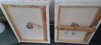
These are the other 2 types of canvas panels tested so far.
The panel on the right in the two photos is the canvas only panel with home made dome , now concave, oops.
This is to minimise exciter noises.
The one on the left used an ordinary 6x4inch 3mm ply ,but glued to the front ,to try and get a more exciting sound.
I would now use a much larger crate ply panel for this last panel , the crate ply is much more exciting, similar to the EPS, but not quite as much.
Steve.
Attachments
By the way, I just checked , and I also cut a hole in the canvas so that the exciter was directly mounted to the 6x4inch ply panel mounted on the front.
When or if I get some more crates , I will remove the 6x4 ply panel and replace it withe the larger crate ply panel.
With the canvas only at the edges as a surround similar to cone speakers.
Steve.
When or if I get some more crates , I will remove the 6x4 ply panel and replace it withe the larger crate ply panel.
With the canvas only at the edges as a surround similar to cone speakers.
Steve.
I was also thinking of trying one of my domes in the centre as the crate ply is more sensitive to exciter noise.
Steve.
Steve.
Although, thinking about it the canvas is probably doing a good job of damping this already?
Steve.
Steve.
Your are right Eric : "one hour".Haha, it took me a while to figure out but I think you meant to say you had one "hour" free, rather than one "our"! Glad to see you are making good use of your "ours"! I know I make a lot of typos myself so don't feel bad....I was just glad I figured it out! (I think).
Anyway, I'm not sure if it's helpful, or even if I did the calculations correctly, but I just did some quick estimates of the speed of bending waves in a typical plywood panel (E=7 GPa, t=4 mm, rho=600 kg/m3), just to give me some perspective. For such a panel I calculated it to be about 50 m/s for a 100 Hz wave and 500 m/s for a 10,000 Hz wave. To traverse 50 cm, then, the 100 Hz wave should take about 10 ms, and the 10,000 Hz wave about 1 ms.
Eric
Thank you for the calculation, it is an order of magnitude I didn't have in mind. 50cm in 10ms at 100Hz it is rather slow compare to what we are use to see... it is even one period. By the way the panel is large (120x45cm).
Roughly estimated, the delay for 50cm @10kHz seems 600µs. Knowing it is poplar 3mm to be checked if it is consistent with the basic formulas.
Christian
Hello SteveWhen I used to build 7ft panels it was easy to hear these frequencies slowly dying away. when the music was paused .
With smaller panels I can't hear this problem.
There is no way a large panel is going to instantly stop vibrating when the exciter stops.
And if it did , dml would be none existent.
The best you could achieve would be a bendingwave speaker, the smaller the better.
Steve.
Interesting remark. It seems there was a movement in the DML building history to come to smaller panels after a period of large one. This leads me to 2 questions (don't worry, i am thinking in a writing way!) :
- Is there a kind of psychoacoustic limit. Above it, the time for the panel to stop emitting is too long?
- Does this phenomena disappear when the panel area is reduced but the 1st resonance kept ? Need to go back to the basic formulas to answer to that...
I think for material and exciter, I tried "enough" at this stage. But there're tons of variation can be play. That depends on time and mood.Hi hkguy6
I was wondering if you put a finish on your ply and eps panels ?
Thanks Pete
Overall I'm satisfy on my EPS, but ply and canvas I will say I enjoy them.
Wave speed and panel surface?
To give a follow-up to posts 6636, 6637, tentative of some math...
f0 ~ pi/A.(D/µ)^0.5, f0 Hz = 1st mode, A m² = panel area, D Nm bending stiffness, µ kg/m² = areal mass
v = (2.pi.f)^0.5.(D/µ)^.25 v m/s = wave speed, f = frequency of interest (100Hz, 10kHz in previous posts)
After some substitutions:
v = (2.A.f0.f)^0.5
So for a given f0 (which gives the bandwidth in the lower frequencies), reducing A, if the formula above is right, reduces the speed for a given frequency, so more time for a given traveling distance. In an other way, the dimensions of the panel are smaller...
So pushing a bit further
Writing A = ka², k being the panel ratio (width/height), the time to travel a/2 (half the height so about from the exciter to the top or bottom edge) t = a/2/v
So t = 1/2/(2.k.f.f0)^0.5
If this time has to be limited, isn't it f0 that matter more than the surface????? Too simple approach? Damping missing?
Christian
Hello EricHere are two good articles. I may have posted these before but some of you may not have seen them. I just re-read them myself and found some things I did not recall. They are not specifically about DML speakers, but are clearly relevant.
Eric
https://www.researchgate.net/public...tics_Tutorial-Part_1_Vibrations_in_Structures
https://www.researchgate.net/public...s_Tutorial-Part_2_Sound-Structure_Interaction
I have also those papers. I found in something probably missing in my previous evaluation of the wave speed : the limitation by the shear speed. The basic illustrations of the different waves are also interesting. In parallel to that, I see now the matrix form used in FEM; I started writing down something around that. First in 1D. Some Python scripts to write after my son has given a look to this method... Long time activity.
Is there something you would push in front front your re-reading?
Christian
- Home
- Loudspeakers
- Full Range
- A Study of DMLs as a Full Range Speaker