...
About measurements, any input to approach the peripheral suspension characteristics is welcome.
About the panel impedance, it is approximated in many paper as resistive but seems not true on all the frequency range. Here also more information welcome
Christian
Well, like you said think in impedance, like in antenna's; Use a dummy load equal to the characteristic impedance of the material to dissipate the remaining energy. Or use a quarter lambda to match the radiating surface to the impedance of the air.
Destroying energy seems easy, i need to experiment to know how easy this is going to be. What can be done is to take a DML put on the exiter and determine the average electrical impedance of the system and write this down. Then find a unwanted resonance, this should be lower/higher the the average impedance. Then take a material that absorbs a lot of energy. Like something foam that does not bounce to much when you throw it on the ground. If you make some supports with this material on the outer edge of the DML and experiment with thickness of the material, there should be a thickness where the resonance is completely eliminated. IN THEORY!
Matching impedance seems difficult, simulation would be key to experiment with this, so that left me with some experimenting in my head, and while i was in the process i accidently i came a cross a special antenna, its a fractal antenna. The idea in the end was to match the speed. The the speed of sound in most materials is not equal to the speed of sound in the air, for 99% of the bandwidth this creates a mismatch in impedance. So if there's a algorithm/pattern that speeds-up the lower frequencies and slows down the higher frequencies. For example maximize the strength(stiffness) for the lower frequencies, then create a longer traveling path for the higher frequencies, like a labyrinth, it should be possible to control the the full bandwidth.
It seems interesting to look at the challenges in RF-world where there already found solutions like log periodic antenna's and UWB antennes.
"Professional tool with expensive add-ons", can you state what tools these might have been? As an engineering student I have access to a fair few programs for research purposes, definitely something I'd like to research, at least in my free time
Lets start with the one you know then try using FEM and CFD at the same time. This could be a VERY helpful tool in this topic!
Finally, I can mark my canvas based DMLs as a finished project. And quite successful I must say. There is something to like about the way the DML panels produce sound. My quick and dirty units have some distortion in the bass and the FR does not seem to be really flat, based on a quick listening test. After a little tightening of the canvas, these will be keepers for my home office background listening - due to their flat format, they will fit the room well. The result encouraged me to experiment further with higher powered multiple exciter panels.

Pelanj.
Can you show a picture of the back of the canvas panel so we can see what you have done.
Plus materials and exciters used.
Steve.
Can you show a picture of the back of the canvas panel so we can see what you have done.
Plus materials and exciters used.
Steve.
+ @hilbrenhilbren,
Do you have an idea of what you plan to look for with the accelerometers?
I suspect that a microphone placed very close to the panel surface might give similar information as an accelerometer.
Eric
On that topic see my tentatives : 4152, 4159, 4160
Yesterday, I made some measurements of this type with a more simple setup :
- iMM6 mic at about 5mm from each point of the panel to measure (reference being the exciter)
- REW with the external time reference (loop back timing reference)
Here is the spectrogram at the exciter (all the frequencies almost aligned near 0)
Here some 40cm from the exciter
So some delay depending of the frequency appears (more delay at low freq, look 300 to 600Hz which is more readible)
Some data treatment is needed do see if we can quantify something.
Nothing for now says the mic is "selective" enough to show what is just in front of it...
Please consider this as raw data.
Christian
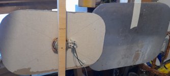
I just made a recording of the 2ply aluminium sheet while moving the microphone around the room.
I was then going to cut the panel down another size to match the size of the card panel.
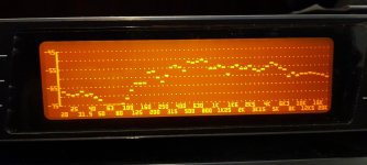
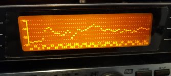
But while I was measuring, I noticed the slight peak at about 5k.
I was a little suspicious of what this was, so turned the panel around.
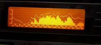
As you can see in the third picture of the reverse frequency response, the dips either side of the 5k peak.
It does not sound too bad in my room , but if up against a reflective wall this could be a problem.
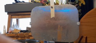
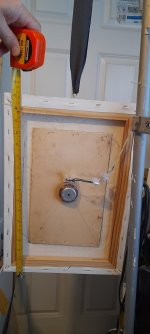
Also I added some weights to the edges , which improved the output in the 90 hz to 200hz area.
This aloud me to turn the volume up a lot higher, although the exciter is now getting hot 🔥 .
This aluminium panel might actually sound better with some sort of frame or damping?
It does wobble and flex a lot, and when holding the sides the sound does not alter too much higher up in frequency range.
So I am going to play around with this one for a little longer and see what happens.
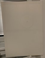
Pic 1 with smaller 12 x7 inch card panel.
Pic 2.
Frequency response of aluminium panel at 1m.
Pic 3.
Response form exciter side of panel same microphone position.
Pic 4.
Panel With the small weights attached.
Steve.
I was then going to cut the panel down another size to match the size of the card panel.
But while I was measuring, I noticed the slight peak at about 5k.
I was a little suspicious of what this was, so turned the panel around.
As you can see in the third picture of the reverse frequency response, the dips either side of the 5k peak.
It does not sound too bad in my room , but if up against a reflective wall this could be a problem.
Also I added some weights to the edges , which improved the output in the 90 hz to 200hz area.
This aloud me to turn the volume up a lot higher, although the exciter is now getting hot 🔥 .
This aluminium panel might actually sound better with some sort of frame or damping?
It does wobble and flex a lot, and when holding the sides the sound does not alter too much higher up in frequency range.
So I am going to play around with this one for a little longer and see what happens.
Pic 1 with smaller 12 x7 inch card panel.
Pic 2.
Frequency response of aluminium panel at 1m.
Pic 3.
Response form exciter side of panel same microphone position.
Pic 4.
Panel With the small weights attached.
Steve.
Attachments
Last edited:
this was the recording i made before adding weights.
forgive the noise of me staggering and climbing around the room.
the loud clapping was at 1m behind the microphone, the microphone was 1m from the panels.
the recording was a m4a , i was testing out a new recording app which i dont think has AVC, i have not noticed it kicking in yet, so could be using this app from now on, but you have to pay to get the mp3.
which i can convert if needed anyway.
the ali panel is on the right grey eps on the left, i had turned down the eps so as to hear the ali a little better.
eps panel turned down 15db.
steve.
Attachments
Opinions please Guys?
I'm considering building a sandwich using EPS as a core substrate with rosewood veneer laminated to the front side (primarily for looks) and aluminium foil on the back side (for low-cost and rigidity.) I am aware that alu foil and rosewood DO NOT have the same compression/stretching ratios!
Therefore, my assumption is that I should pick up some level of 2nd harmonic distortion because the rarefaction will have a different amplitude to the compression cycles...
But before I go to all the effort of building this conglomerate, is there anything else I should be assuming?
Christian/Homeswing/Hilbren???+ @hilbren
On that topic see my tentatives : 4152, 4159, 4160
Yesterday, I made some measurements of this type with a more simple setup :
just to give you an idea
- iMM6 mic at about 5mm from each point of the panel to measure (reference being the exciter)
- REW with the external time reference (loop back timing reference)
Here is the spectrogram at the exciter (all the frequencies almost aligned near 0)
View attachment 1092308
Here some 40cm from the exciter
View attachment 1092309
So some delay depending of the frequency appears (more delay at low freq, look 300 to 600Hz which is more readible)
Some data treatment is needed do see if we can quantify something.
Nothing for now says the mic is "selective" enough to show what is just in front of it...
Please consider this as raw data.
Christian
it looks like there's a cross-over (with group delay) involved at the 150Hz mark, or standing waves at 80hz via a subwoofer.... What's going on there??
Hi Steve,Hi burntcoil.
Long time no hear.
I just got back from France yesterday and thought of you while I was over there, wondering which side of the channel you were on?
Do you still have dml projects going on ?
I am back in the UK due to cardiac problems. It’s been a tough two years. I am just getting back to DML design and build. I’ll post some new thoughts once I have tried a few new experiments.
Burnt
Hi AndreChristian/Homeswing/Hilbren???
it looks like there's a cross-over (with group delay) involved at the 150Hz mark, or standing waves at 80hz via a subwoofer.... What's going on there??
No crossover, no sub... This is my plywood panel playing full range with the mic being about 5mm from the surface (so very close).1st is at the exciter axis, 2nd is a point in the middle of the width, 40cm below the exciter in vertical. The idea behind those measurements is to see if the mic collects the panel behavior just in front of it, to try to evaluate the wave speed into the panel, the absorption, and the reflected waves. So nothing like a standard measurement like we see more usually around 1m. Nevertheless, I am surprised too. At this point nothing says this measurement makes sense. The purpose, as I am interested also in seeing how the panel behaves, was to share an example of close mic measurement as Eric proposed in a post just before.
Christian
Hello Burnt,Hi Steve,
I am back in the UK due to cardiac problems. It’s been a tough two years. I am just getting back to DML design and build. I’ll post some new thoughts once I have tried a few new experiments.
Burnt
Before posting, about 2 years ago, I read this thread from A to Z (not sure the reading was always 100% efficient!) so your previous contributions. I am pleased to see your name again. Welcome back (sorry if my English needs some improvements). I hope those important health problem are behind you.
Christian
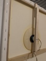
My panels are 50 x 70 cm, exciters DAEX25VT-4. There is a 15 cm diameter 4mm poplar plywoid disc with a 10 mm hole. Glued with silicone, the edges are also glued to the frame with silicone. The plates are offset around 2/3 in both directions. I do not remember exactly, I made the panels long time ago and only yesterday mounted the exciters. The spine is made of 12 mm birch plywood leftovers, exciters are glued to the spine with gel CA glue.
Some pictures are attached. I found the source of distortion - one of the exciters was not glued properly by the double sided tape and fell partially off. After a mighty push, it stays in place fine. I am running these now with a mini class D amp with Bluetooth. Just placed on my desk near a wall. Maybe I will hang them properly one day🙂 I get surprisingly low bass at low volumes.
Some pictures are attached. I found the source of distortion - one of the exciters was not glued properly by the double sided tape and fell partially off. After a mighty push, it stays in place fine. I am running these now with a mini class D amp with Bluetooth. Just placed on my desk near a wall. Maybe I will hang them properly one day🙂 I get surprisingly low bass at low volumes.
Attachments

That is kind of you to say Christian and it is much appreciated. Your English is just fine!Hello Burnt,
Before posting, about 2 years ago, I read this thread from A to Z (not sure the reading was always 100% efficient!) so your previous contributions. I am pleased to see your name again. Welcome back (sorry if my English needs some improvements). I hope those important health problem are behind you.
Christian
Best regards
Burnt
Christian,Nothing for now says the mic is "selective" enough to show what is just in front of it...
I submit (for now!) that the fact that the response of the mic in our tap tests:
https://www.diyaudio.com/community/...r-dml-design-and-analysis.383567/post-6954047
suggests that the mic is indeed quite selectively showing what is exactly in front of it.
Using the mic as if it is an accelerometer, I can often identify the frequencies and "identities" (i,e: m,n) of the first 10 to 15 natural frequencies of any panel.
What is it in your results that suggests that the mic is not selective enough? What are your expectations, and how were they not met?
Eric
It's good to hear that you are OK , and am looking forward to reading about your ideas.Hi Steve,
I am back in the UK due to cardiac problems. It’s been a tough two years. I am just getting back to DML design and build. I’ll post some new thoughts once I have tried a few new experiments.
Burnt
Steve.
I have 4 size of canvas total 12 pairs of panel on hand.The result encouraged me to experiment further with higher powered multiple exciter panels.
30" x 40" was give up because lack of efficiency and bad tonal balance. However it does has very good sound stage, layers separation.
60" x 80" was almost give up. Sound quite boring and didn't see any advance on canvas this large. Even with 1 to 4 exciters I tried.
50" x 60" I have to spend more time to test. This has bigger imaging size of instrument then the 40" x 50". But have problems here and there waiting to solve.
40" x 50" linen canvas is my favourite. Lively sound and even more musical then my beloved EPS. Just the efficiency not so good, nothing else to complain.
All canvas use 40W PUI exciter and without spine. Hard mounted (G clamp) on a diy stand.
Hkguy6.
WOW, I thought that pelanj panels might be too big 😃.
It would be interesting to see some measurements and maybe a recording.
My main worry would be the panel flapping especially at higher volumes with such large uncontrolled areas .
Have you tried the smaller panels similar to mine and jaxboy?
You will still get good LF down to 40hz if using larger ply panels similar to my picture below.
Although for serious listening I would XO above 100hz.
Pva was used to glue on the exciter and 3mm ply that is all that is needed for good results.
Water can be used to shrink the canvas if necessary.
Tweaking can improve on this basic panel if wanted.
This panel has been re adjusted a few times already.
Steve.
Attachments

I also think mine are a bit on the large side. Next will be definitely smaller size and in 2.1 configuration with a subwoofer. I also want to try foam, fiberglass and other materials, this got me hooked to DMLs. Performance to box volume ratio is just so great, especially for my smaller rooms. These inexpensive panels just confirm my personal view that point source, even dispersion and crossover less in the critical band are more important than ruler flat frequency response to my ears.
Pelanj.
With a little eq or actually fixing the problem in the 800hz area, the response in my plot is pretty flat from 20k down to 250hz.
Steve.
With a little eq or actually fixing the problem in the 800hz area, the response in my plot is pretty flat from 20k down to 250hz.
Steve.
Yes, that is true - I wanted to say that even without any EQ at the moment (which is for sure necessary with my build) and running full range on low levels, the sound is very enjoyable. Especially stringed instruments, percussions and vocals sound really life like. I am used to hearing this from my huge 4 way horn stack or unity/synergy builds with planar HF, but the area/volume occupied by speakers is incomparable and also I need to sit a bit further back.
The panels work surprisingly well as near field speakers on my desk.
The panels work surprisingly well as near field speakers on my desk.
- Home
- Loudspeakers
- Full Range
- A Study of DMLs as a Full Range Speaker