Hi pwayLog SPL (ie decibels) would be the correct setting for almost every purpose, as our ears respond logarithmically to SPL. The point of logarithms is that they convert power law relations into linear relations, eg giving a straight-line rolloff where in the linear context its really a precipitous power-law cliff.
Your > or < comparison is presumably just the 'apparent' height of the trace - is that what you mean?
Yep - and why ápparent' - the trace is recording the SPL received by the mic at each frequency.
I'm aware that we hear non linearly - The test signals are of the same amplitude so there's a greater density of signals in the linear sweep case at the higher frequencies - hence the higher SPL recorded by the mic at these frequencies compared to the log case. (I have ear plugs in so I can't tell if the two sweeps sound different to me - 😊)
How would each sweep result compare with a plot of individual tones over the same frequency range?
In the linear sweep case- I don't get any precipitous cliff - it's just a milder slope to the upper limit.
My HF hearing is somewhat impaired (age and tinnitus 🙁) but if I adjust the treble output to approach a "studio monitor" level of flatness on either a log or linear scale, the sound is %$#@ high pitched and awful even to me, let alone a young person.
If a flat response actually sounds as above, what then is a 'good' target slope for a speaker for the range >1kHz ?
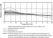
I'm forgetting that published response curves are measured in an anechoic chamber.
Maybe these - the second indicates a 10dB roll off in room approx = anechoic flat
Maybe these - the second indicates a 10dB roll off in room approx = anechoic flat
Attachments
Last edited:
Forgive me for belabouring the point, but how did you connect the two exciters? If everything else checks out, the polarity of the exciters is the only obvious potential problem that occurs to me.Regular bookshelf speakers sound fine with the amp and reach a reasonable output level. I double checked all the connections as well. Regarding adhesion I didn't want to commit to using the vhb-tape before I found a good position on the panel, so I fixated the exciters with tape for testing. Does not using the adhesive reduce the volume that much? I think my comparison cardboard may be too old/soggy so I'm going hunting for some better panel material tomorrow.

Dmlquasar.
thick heavy corrugated cardboard will be very hard to drive, you don't state what card you are using ?
I used to use a thickness of less than 3mm ,which sounded fine at the time , and was free.
This was with a single 10watt exciter.
I would recommend using a single exciter for testing, it's much easier, and would allow you to slide the exciter around the panel to find a good place to mount, if you did not want to use one of the recommended positions ?
1cm thick plastic is far too thick and is very hard to drive.
A 25watt exciter should drive most reasonable panel materials to a good in room level.
If at a later date you still wanted to use more exciters per panel you would still have that option, but don't expect a great difference .
EPS so far produces the loudest volume for a dml panel and only one exciter is needed.
But it does need a little work to make it sound good.
The very low quality ply I am testing at the moment is also very efficient and seems very promising, but also could do with a bit of work to improve things.
Steve.
Christian.
I have no idea of its density.
I'm not even sure where you could buy this low quality ply ?
I put up one of my low quality EPS panels coated in pva.
I would expect to have to adjust the volume by about 10db on my deq to match a 3mm ply.
But this material only needed about 4db .
I do have a similar size 3mm ply I can match it to and compare ?
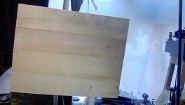
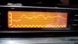
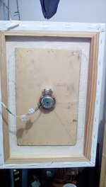
These pictures show the new 4 strip panel.
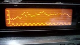
The second picture shows the new response, not as flat as the 3 strip panel ,with a more exaggerated hump just below 1k.
The third picture shows what happens when I hold the ends of the panel in my hands (the microphone was just placed on the side).
The low frequency hump increases and moved down in frequency to about 60hz.
I did try using weights (sound bridges ?) But the blu-tack wasn't strong enough to hold them on, as this made the panel vibrate more, this is not what I would normally want to happen.
Steve
I have no idea of its density.
I'm not even sure where you could buy this low quality ply ?
I put up one of my low quality EPS panels coated in pva.
I would expect to have to adjust the volume by about 10db on my deq to match a 3mm ply.
But this material only needed about 4db .
I do have a similar size 3mm ply I can match it to and compare ?
These pictures show the new 4 strip panel.
The second picture shows the new response, not as flat as the 3 strip panel ,with a more exaggerated hump just below 1k.
The third picture shows what happens when I hold the ends of the panel in my hands (the microphone was just placed on the side).
The low frequency hump increases and moved down in frequency to about 60hz.
I did try using weights (sound bridges ?) But the blu-tack wasn't strong enough to hold them on, as this made the panel vibrate more, this is not what I would normally want to happen.
Steve
Attachments
Sorry, I assumed you were talking about a linear vertical (SPL) axis.Hi pway
Yep - and why ápparent' - the trace is recording the SPL received by the mic at each frequency.
I'm aware that we hear non linearly - The test signals are of the same amplitude so there's a greater density of signals in the linear sweep case at the higher frequencies - hence the higher SPL recorded by the mic at these frequencies compared to the log case. (I have ear plugs in so I can't tell if the two sweeps sound different to me - 😊)
How would each sweep result compare with a plot of individual tones over the same frequency range?
In the linear sweep case- I don't get any precipitous cliff - it's just a milder slope to the upper limit.
My HF hearing is somewhat impaired (age and tinnitus 🙁) but if I adjust the treble output to approach a "studio monitor" level of flatness on either a log or linear scale, the sound is %$#@ high pitched and awful even to me, let alone a young person.
If a flat response actually sounds as above, what then is a 'good' target slope for a speaker for the range >1kHz ?
I don't know what the utility of the linear sweep is, unless you're maybe investigating a small range of frequencies. Seems to me that to use a linear sweep means that exponentially more attention is paid to the higher frequencies than is warranted.
Last edited:
I connected them in series, so + to -. The differently sized terminals on the exciters I have make that pretty difficult to mess up.Forgive me for belabouring the point, but how did you connect the two exciters? If everything else checks out, the polarity of the exciters is the only obvious potential problem that occurs to me.
I think I underestimated the impact of material Thickness/mass in general, I just don't have any really light material at hand to test with but I will probably get some cheap thin plywood today. The Acrylic would've just been nice optics wise and convenient since I already had it, but it seems it just isn't a good fit.Dmlquasar.
thick heavy corrugated cardboard will be very hard to drive, you don't state what card you are using ?
I used to use a thickness of less than 3mm ,which sounded fine at the time , and was free.
This was with a single 10watt exciter.
I would recommend using a single exciter for testing, it's much easier, and would allow you to slide the exciter around the panel to find a good place to mount, if you did not want to use one of the recommended positions ?
1cm thick plastic is far too thick and is very hard to drive.
A 25watt exciter should drive most reasonable panel materials to a good in room level.
If at a later date you still wanted to use more exciters per panel you would still have that option, but don't expect a great difference .
EPS so far produces the loudest volume for a dml panel and only one exciter is needed.
But it does need a little work to make it sound good.
The very low quality ply I am testing at the moment is also very efficient and seems very promising, but also could do with a bit of work to improve things.
Steve.
I will probably end up using the recommended positions anyway, I just wanted to confirm it for myself first.
The amp I'm using has to drive a 8 Ohm impedance load minimum, that's why I did not want to use it with a single exciter per channel. But since I will get the plywood anyway I might go for a configuration of 4 panels with one exciter each. Thank's for the advice!
Steve,Christian.
I have no idea of its density.
I'm not even sure where you could buy this low quality ply ?
I put up one of my low quality EPS panels coated in pva.
I would expect to have to adjust the volume by about 10db on my deq to match a 3mm ply.
But this material only needed about 4db .
I do have a similar size 3mm ply I can match it to and compare ?
These pictures show the new 4 strip panel.
The second picture shows the new response, not as flat as the 3 strip panel ,with a more exaggerated hump just below 1k.
The third picture shows what happens when I hold the ends of the panel in my hands (the microphone was just placed on the side).
The low frequency hump increases and moved down in frequency to about 60hz.
I did try using weights (sound bridges ?) But the blu-tack wasn't strong enough to hold them on, as this made the panel vibrate more, this is not what I would normally want to happen.
Steve
My question was not in the idea to buy the same but to see how the density evaluation match with your SPL evaluation. The measure of the weight on a digital kitchen balance and the dimensions is enough... It is how I proceed. For the thickness, a caliper is the right tool.
Christian
Hello Eucy,I'm forgetting that published response curves are measured in an anechoic chamber.
Maybe these - the second indicates a 10dB roll off in room approx = anechoic flat
I just had a look to REW and I don't see this log/lin option in the measurement panel. I see it in the wave generator function but it is not in my opinion the way... The principle behind REW measurement is if I remember from M Farina's work; based on log sweep then the result in convolved with an inverse sweep (we don't see this step) to give the impulse response. Then some FFT is applied to give the FR. This is fully automated in the "measurement function". Is it what you use?
About the target response, I would be cautious on the one to use. 2 aspects are hidden behind : the in axis FR, the off axis FR. The curves you refer to are adapted to standard loudspeaker. The directivity of DML are very different... So does it apply? It remind me the "house curve" which in the same idea help in adjusting system in the condition the loudspeaker and the room are not too far from what was expected... Please consider it is an opinion... no strong scientific background on that.
Christian
Hi ChristianHello Eucy,
I just had a look to REW and I don't see this log/lin option in the measurement panel. I see it in the wave generator function but it is not in my opinion the way... The principle behind REW measurement is if I remember from M Farina's work; based on log sweep then the result in convolved with an inverse sweep (we don't see this step) to give the impulse response. Then some FFT is applied to give the FR. This is fully automated in the "measurement function". Is it what you use?
About the target response, I would be cautious on the one to use. 2 aspects are hidden behind : the in axis FR, the off axis FR. The curves you refer to are adapted to standard loudspeaker. The directivity of DML are very different... So does it apply? It remind me the "house curve" which in the same idea help in adjusting system in the condition the loudspeaker and the room are not too far from what was expected... Please consider it is an opinion... no strong scientific background on that.
Christian
Yes I use the measurement function - The log/linear comment was just me thinking a switch from log to linear at some frequency point may give a more balanced result.
I find it uncomfortably weird that we place so much emphasis on in-room sweep test results when in truth we don't know what they mean in a comparative/global sense. We can use them for localised comparisons in the same setting and conditions, and with the same equipment, but even looking at localised humps and suck-outs is fraught with risks due to un-measurable room effects. Having some form of rule of thumb guide as to the likely overall effect of a 'normal' (Yep, I know, there isn't one) room (or a range of room types) on anechoic results would be some form of benchmark - even if only a wobbly one it would/could be better than none.
Maybe need to go test in the Mojave Desert, or (slightly) more locally for me - the Nullabor Plain. I did read that Harbeth in the UK used to (perhaps still do) test in their carpark 👍.
As for on/off axis, I'm only interested in on axis at this point - if we can't reliably and definitively analyse on axis, there's no chance off axis.
Thanks and Cheers
Eucy
Last edited:
Eucy.
a microphone position of about 30cm to a maximum of 1m should give you a good idea of what your panels are putting out.
beyond this the room will have serious influence on the plot below 500hz or so ?
measurements from your seating position are useful to you as it is your response in your room.
how useful anechoic measurements would be is debatable, with no rear reflections from the inside walls ?
Steve.
Dmlquasar.
I presume you ment from - on the first exciter to + on the second exciter ?
Steve.
I presume you ment from - on the first exciter to + on the second exciter ?
Steve.
I'm forgetting how this started , I just used this handy material I just had lying around ,with the intention of trying out some of my ideas to improve the sound of the art panel .
So I was a little taken aback by the improvement made by this material.
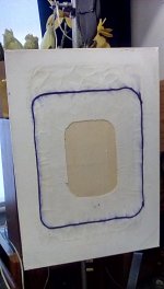
As you can see in these pictures ,I had to cut out the old 6x4inch x 2mm ply panel and glue in the larger lower quality panel.
This leaves the new panel undamped by the canvas ,over the 6x4inch gap in the canvas.
This works well with this material, the panel could even be bigger with less canvas covering the ply ?
If anyone was building a new art panel or thinking of improving the panel they have already built, I would recommend this.
This is a vast improvement.
Steve.
So I was a little taken aback by the improvement made by this material.
As you can see in these pictures ,I had to cut out the old 6x4inch x 2mm ply panel and glue in the larger lower quality panel.
This leaves the new panel undamped by the canvas ,over the 6x4inch gap in the canvas.
This works well with this material, the panel could even be bigger with less canvas covering the ply ?
If anyone was building a new art panel or thinking of improving the panel they have already built, I would recommend this.
This is a vast improvement.
Steve.
Attachments
Hi Eucy,
Your post #5,550 is very interesting and brings up interesting questions. It is becoming more clear to me that the "DML" is just the sound board speaker. Meaning that the panel is coloring or giving its unique sound interpolation of the exciter driving the panel.
In testing the FR of the panel one drives a single frequency at a time and takes the power spectrum of that frequency the panel is reproducing converting the time domain signal into the frequency domain and the amplitude of the power spectrum is the FR at that frequency.
So in my option the FR is just a single "sin wave frequency" response curve for that panel with the exciter at a particular position. Move the exciter and you get a different FR response i.e. different sound and change the coating and a different FR and change the panel material different FR.
To get a better handle on how the panel will reproduce music is to use a noise source instead single sin wave frequency. I have not found a way to do that in REW yet may be some one can enlighten me on how REW can do this. I writing a LabView program since I have the software and generating a power spectrum response in real time of what the microphone is hearing. The tricky part right now is getting the microphone calibrated to give the SPL. In the end it just boils down to what coloration of sound the panel one likes and go with that.
Cheers,
Steve
Yes, that's what I meant.Dmlquasar.
I presume you ment from - on the first exciter to + on the second exciter ?
Steve.
Hello TagisHi Eucy,
Your post #5,550 is very interesting and brings up interesting questions. It is becoming more clear to me that the "DML" is just the sound board speaker. Meaning that the panel is coloring or giving its unique sound interpolation of the exciter driving the panel.
In testing the FR of the panel one drives a single frequency at a time and takes the power spectrum of that frequency the panel is reproducing converting the time domain signal into the frequency domain and the amplitude of the power spectrum is the FR at that frequency.
So in my option the FR is just a single "sin wave frequency" response curve for that panel with the exciter at a particular position. Move the exciter and you get a different FR response i.e. different sound and change the coating and a different FR and change the panel material different FR.
To get a better handle on how the panel will reproduce music is to use a noise source instead single sin wave frequency. I have not found a way to do that in REW yet may be some one can enlighten me on how REW can do this. I writing a LabView program since I have the software and generating a power spectrum response in real time of what the microphone is hearing. The tricky part right now is getting the microphone calibrated to give the SPL. In the end it just boils down to what coloration of sound the panel one likes and go with that.
Cheers,
Steve
I agree on the view of a DML as a soundboard.
The coloration is a possibility when we think how a DML works, based on modes. In practice, it seems DML are appreciated meaning the coloration is not very strong? I see 2 theoretical possible causes : one frequency has not the right level (too high, too low), one frequency is not in the original signal. The spectral contamination can give an input for the second, the question being which level of added frequencies we can hear. For the first one, a qualification of the FR humps might give also a metric (see M Floyd Toole's book about the audibility of high Q hump). Some inputs, papers on that might be interesting.
About the way of measuring, I think your view is not correct. The main intermediate result from REW is the impulse response (IR) not a power spectrum. REW is based on the use of a logsweep which is recorded and then convoluted with a reverse logsweep. The magic is it gives the IR and even harmonic distorsion. This one last step of a long history of techniques to get the response of a system. As it is based on the IR, it is based on the full spectrum not only one frequency. The IR gives a full view of a system response. What is more difficult for me is the way to use this IR due to the room additions. The resulting FR is strongly dependent on the used method (FFT with long or short window, frequency dependent windowing, spectrogram). This is the tricky point.
The method you think about is as I understand it far in the history. It seems like playing a pink noise and looking at the result in different bands with a RTA (Real Time Analyser). REW has all the tools for that (if I understood your intention). You might have a look to "Moving Microphone Technique", I have posted some notes in #4488 about it. It is an easy technique with quite good results. The main drawback is the time information is lost, and the noise rejection is lower.
In your method, the tricky point is not in the microphone (many of them have low errors compare to the loudspeaker), it is in the filtering of the signal collected by the microphone. It is a property of using pink noise with constant Q filter to get the same output on each band.
Christian
Hello Eucy,Hi Christian
Yes I use the measurement function - The log/linear comment was just me thinking a switch from log to linear at some frequency point may give a more balanced result.
I find it uncomfortably weird that we place so much emphasis on in-room sweep test results when in truth we don't know what they mean in a comparative/global sense. We can use them for localised comparisons in the same setting and conditions, and with the same equipment, but even looking at localised humps and suck-outs is fraught with risks due to un-measurable room effects. Having some form of rule of thumb guide as to the likely overall effect of a 'normal' (Yep, I know, there isn't one) room (or a range of room types) on anechoic results would be some form of benchmark - even if only a wobbly one it would/could be better than none.
Maybe need to go test in the Mojave Desert, or (slightly) more locally for me - the Nullabor Plain. I did read that Harbeth in the UK used to (perhaps still do) test in their carpark 👍.
As for on/off axis, I'm only interested in on axis at this point - if we can't reliably and definitively analyse on axis, there's no chance off axis.
Thanks and Cheers
Eucy
I understand your question... how to reduce or identify what is added by the room.
Saying that the change from log to lin is not a solution. It might be a tool to have another look at the FR in the low frequencies. Up to now it is not in the missing tool for me.
About the room, as you say, if the goal is a comparison between different solution, keeping the source and the mic at the same point is ok. To make analysis of a design, changing the speaker or mic position helps. A large room or even just a standard garden (french house scale, not a castle or even a desert ;-) ) also help. I think some DIYer lift the speaker on a structure (a ladder?) in their garden to avoid the reflections. DML have a drawback in outside conditions which is the possible sensitivity to the wind (large dimensions, small foot print, weak membrane).
I spent time at my beginning with DML to try to understand where such problem comes to end on the fact that most of the problems (not saying all) we want to solve are from the panel. This is probably not so surprising due to the reputation of the DML to have a low room influence (coming from its diffuse nature = the sound source is not located at a single point for all the frequencies).
So at the moment, I don't worry really about the room effect as I was before coming from standard loudspeaker paradigm.
As mentioned by Spedge : mic at 1m (my tests shown me that 30cm is a bit short even for a 30cm panel - I made some series of measurements 0.25m, 0.5m, 1m, 2m showing the FR becomes "stable" between 0.5 and 1m) with some frequency dependent windowing or wavelet spectrogram do a big job. This even is more true that our frequency range of interest is mainly above 100 or even 200Hz.
Christian
Sarathcassca,Could you please help in choosing exciter out of the below models which are available here. Attached the response graphs given in its data sheets.
DAEX25Q and DAEX32U are rated at 20w, and DAEX25 at 5w, and DAEX25CT at 10w
The more popular one DAEX25FHE is not available here and is out of stock.
Thinking of using them with Canvas panels running full range to start with.
One common thing in the data sheet graphs is that all the models have weaker top end / treble after around 10KHz. And for DAEX32U we have a dip at 700Hz. Do we see similar behavior when used with plywood or canvas panels
I had a deeper look on the possible exciters you listed... unfortunately I can't find one I would say "yes this one!". No good choice according to my criteria (force factor, inductance...). I hope you will find more possibilities or the advice of someone else about this list. The DAEX32U has even a strange suspension behavior. For sure without more information, I won't go for that one.
Christian
Christian.
the exciter is now glued firmly to the 4 strip panel.
I noticed that when the sun shines ,the light shines through the panel, which the other plys do not.
The small 3mm 286mm x 176mm is about 64g .
The strips on the larger panel seem to measure slightly less than 3mm sometimes getting close to 2.5mm ?
I've been looking, to try to find out what the material crates are made out of , without luck so far.
Steve.
Thanks Christian and SpedgeHello Eucy,
I understand your question... how to reduce or identify what is added by the room.
Saying that the change from log to lin is not a solution. It might be a tool to have another look at the FR in the low frequencies. Up to now it is not in the missing tool for me.
About the room, as you say, if the goal is a comparison between different solution, keeping the source and the mic at the same point is ok. To make analysis of a design, changing the speaker or mic position helps. A large room or even just a standard garden (french house scale, not a castle or even a desert ;-) ) also help. I think some DIYer lift the speaker on a structure (a ladder?) in their garden to avoid the reflections. DML have a drawback in outside conditions which is the possible sensitivity to the wind (large dimensions, small foot print, weak membrane).
I spent time at my beginning with DML to try to understand where such problem comes to end on the fact that most of the problems (not saying all) we want to solve are from the panel. This is probably not so surprising due to the reputation of the DML to have a low room influence (coming from its diffuse nature = the sound source is not located at a single point for all the frequencies).
So at the moment, I don't worry really about the room effect as I was before coming from standard loudspeaker paradigm.
As mentioned by Spedge : mic at 1m (my tests shown me that 30cm is a bit short even for a 30cm panel - I made some series of measurements 0.25m, 0.5m, 1m, 2m showing the FR becomes "stable" between 0.5 and 1m) with some frequency dependent windowing or wavelet spectrogram do a big job. This even is more true that our frequency range of interest is mainly above 100 or even 200Hz.
Christian
I do test @ 900mm and @ listening positions - I'll continue on as the Nullabor Plain is just too far away. 🙂
Cheers
Eucy
- Home
- Loudspeakers
- Full Range
- A Study of DMLs as a Full Range Speaker