pway,We agree that 3:1 might be a good aspect ratio. Ive only so far tested 2:1 but I take your experience as further supporting evidence!
Back when Burntcoil made the famous tall blondes, I started looking at how the distribution of natural frequencies was affected by aspect ratio by doing FEM. What I noticed was that as the aspect ratio gets higher, the spacing of the natural frequencies along the frequency axis becomes more regular:

Here's the full post from back then:
https://www.diyaudio.com/community/...s-as-a-full-range-speaker.272576/post-6129119
The plot includes all modes, where probably I should have included only the odd, odd modes, but the trend is the same. At low aspect ratios the spacing of modes is irregular, while at higher aspect ratios the spacing of the modes just above the fundamental becomes pretty uniform.
I've only recently started testing high aspect ratio panels. But I've had pretty good results lately with aspect ratios in the range of 3.4 to 4.0. The uniform spacing of modes doesn't guarantee a flat frequency response at the low end, but it gives you a fighting chance!
Eric

Hello Eucy
This is a relation about efficiency. The highest A or R in this relation, the highest SPL. This relation doesn't give the F0 which is related to an other "A" which is the panel area and also the form factor... so additional math needed to have a better picture including what about the SPL and F0 following the choice of a and b.
Christian
Hi Christian - Sorry, a misundercanstumble on my part - pays to look more before leaping 😉😉
Eucy
I can certainly relate to what Steve says. I'm having difficulty keeping up with one day's posts, still less reading the literature and the previous discussions, still less starting on new experiments. 🙁Okay, so by "edge and corner modes" you did not mean the flapping edges and corners of a free panel, but rather something else.
That is a great link by the way. And it references a lot of the seminal work in this area, which reminds me I have some reading to do!
But I'm still not following what you mean by edge and corner modes. I skimmed the article twice but still didn't see it referenced (although I guess you saw that too). Is there another paper that talks about edge and corner modes? I don't ever recall seeing that terminology, and I'm still confused what they are.
The sources I have found mainly talk about how, below fc, the modes with the highest radiation efficiency are the odd, odd modes. I have always assumed that the reason for this is that those modes (like the 1,3) shown below, are unbalanced and hence not fully "cancelling". That is it has two regions that are out of phase with the one other region.
View attachment 1045546
While modes like this (1,4) on the other hand, have identical regions moving in opposite directions, and hence tend to cancel each other in the far field.
View attachment 1045547
But this effect is not dependent on damping, so perhaps it is still not what you are talking about.
Eric
I could not find the paper I had in mind regarding corner/edge modes, so I had to search again. One in particular may be of interest looks like a sustained investigation of this effect in guitars. https://doi.org/10.1121/1.3592235 (Note sci-hub is your friend for accessing all these)
A couple more mentions: (Cutting and pasting from PDF screws up fonts and formatting)
The radiation efficiency of baffled plates and strips G. Xie et al:
https://doi.org/10.1016/j.jsv.2003.12.025
There is some fluctuation of the numerical result between the fundamental natural frequency (at 50 Hz) and about 500 Hz. It is well known that this frequency range is dominated by ‘corner’ modes(modes with ka51 and kb51). For these modes sound radiation is effectively limited to the corners of the plate and the radiation efficiency is approximately constant with frequency. As frequency increases, the radiation efficiency increases until the critical frequency. This increasing region corresponds to the occurrence of ‘edge’ modes (kao1; kb > 1 or ka > 1; kbo1) where radiation isfrom two opposite edges
Sound radiation from rectangular baffled and unbaffled plates, Putra et al
https://doi.org/10.1016/j.apacoust.2010.06.009"Between the first natural frequency of the plate and the critical frequency, acoustic short-circuiting occurs in the so-called corner and edge mode regions. The radiation efficiency in these regions can be described by asymptotic formulae."
A RADIATION EFFICIENCY FOR UNBAFFLED PLATES WITH EXPERIMENTAL VALIDATION Oppenheimer et al
https://doi.org/10.1006/jsvi.1996.0609
A radiation efficiency for frequencies below the plate critical frequency has been developed by averaging radiation efficiencies of the modes of a simply supported plane-baffled plate [1, 2]. In this paper this expression is called the (subcritical) baffled plate radiation efficiency: sbaf=scorner+sedge , fQfc , (2) in which scorner and sedge are the modal average radiation efficiences for the so-called corner and edge modes, and fc is the critical frequency of the plate. Corner modes radiate primarily from regions near the corners of a plate (see Figure 1), and edge modes radiate primarily from regions along the plate perimeter
Note in searching its better to use "corner modes" because edge modes also refers to true modes along the edge AKA Lamb waves.
Paul
Ericpway,
Back when Burntcoil made the famous tall blondes, I started looking at how the distribution of natural frequencies was affected by aspect ratio by doing FEM. What I noticed was that as the aspect ratio gets higher, the spacing of the natural frequencies along the frequency axis becomes more regular:
View attachment 1045638
Here's the full post from back then:
https://www.diyaudio.com/community/...s-as-a-full-range-speaker.272576/post-6129119
The plot includes all modes, where probably I should have included only the odd, odd modes, but the trend is the same. At low aspect ratios the spacing of modes is irregular, while at higher aspect ratios the spacing of the modes just above the fundamental becomes pretty uniform.
I've only recently started testing high aspect ratio panels. But I've had pretty good results lately with aspect ratios in the range of 3.4 to 4.0. The uniform spacing of modes doesn't guarantee a flat frequency response at the low end, but it gives you a fighting chance!
Eric
One point I have in mind now from the recent posts is the difference in stiffness in the both direction for a 3 layer ply and a 5 layer ply.
Going back in the post #1189 I see that Burntcoil's ply in the TallBlond is 3 layers... so possible important difference in the stiffness along or across the grain.
So I wonder if really the good results of such design are explained by the frequency spacing.
In his paper about the Tall panel, Burntcoil explains his method for damping with sorbothane. I don't remember many posts around that despite it seems fundamental. Have you already experienced it?
Christian
Christian:
Eric:
It stands to reason that an elongated panel would give better spacing at low frequencies than a square one, because you are giving the waves a longer and a smaller distances to traverse, accomodating a greater range of wavelengths.
This is what Im aiming for with non-rectilinear shapes. Not just to eliminate the most obvious standing waves, and to randomise, but to give the waves a smooth distribution of path lengths across the panel body in any direction, in the hope that that relates to a more even distribution of SPL with freq. At the lowest frequencies, again I hope that the addition of some small number of lobes of different resonant frequencies could be designed to augment the bass - ie fill in gaps at the bottom end.
So I wonder if really the good results of such design are explained by the frequency spacing.
Eric:
The uniform spacing of modes doesn't guarantee a flat frequency response at the low end, but it gives you a fighting chance!
It stands to reason that an elongated panel would give better spacing at low frequencies than a square one, because you are giving the waves a longer and a smaller distances to traverse, accomodating a greater range of wavelengths.
This is what Im aiming for with non-rectilinear shapes. Not just to eliminate the most obvious standing waves, and to randomise, but to give the waves a smooth distribution of path lengths across the panel body in any direction, in the hope that that relates to a more even distribution of SPL with freq. At the lowest frequencies, again I hope that the addition of some small number of lobes of different resonant frequencies could be designed to augment the bass - ie fill in gaps at the bottom end.
No, they didn't mention edge modes explicitly, but used similar cancellation logic to explain why damping will give a non-zero radiation efficiency. (Note edge/corner modes have nothing to do with damping per se, we just happen to be discussing both effects.)Okay, so by "edge and corner modes" you did not mean the flapping edges and corners of a free panel, but rather something else.
That is a great link by the way. And it references a lot of the seminal work in this area, which reminds me I have some reading to do!
But I'm still not following what you mean by edge and corner modes. I skimmed the article twice but still didn't see it referenced (although I guess you saw that too). Is there another paper that talks about edge and corner modes? I don't ever recall seeing that terminology, and I'm still confused what they are.
The sources I have found mainly talk about how, below fc, the modes with the highest radiation efficiency are the odd, odd modes. I have always assumed that the reason for this is that those modes (like the 1,3) shown below, are unbalanced and hence not fully "cancelling". That is it has two regions that are out of phase with the one other region.
View attachment 1045546
While modes like this (1,4) on the other hand, have identical regions moving in opposite directions, and hence tend to cancel each other in the far field.
View attachment 1045547
But this effect is not dependent on damping, so perhaps it is still not what you are talking about.
Eric
I guess the problem with even modes is twofold. First, they don't have a central antinode, some of which will survive cancellation due to damping, and which will be larger anyway if the exciter is centrally placed. Secondly, after cancellation you are still left with a + on one side and a - on the other side. Which even if they can reach the far field will cancel out at your listening location directly in front - which I think is what you were saying.
Hello Paul,It stands to reason that an elongated panel would give better spacing at low frequencies than a square one, because you are giving the waves a longer and a smaller distances to traverse, accomodating a greater range of wavelengths.
This is what Im aiming for with non-rectilinear shapes. Not just to eliminate the most obvious standing waves, and to randomise, but to give the waves a smooth distribution of path lengths across the panel body in any direction, in the hope that that relates to a more even distribution of SPL with freq. At the lowest frequencies, again I hope that the addition of some small number of lobes of different resonant frequencies could be designed to augment the bass - ie fill in gaps at the bottom end.
I agree on the "theoretical" interest of elongated rectangle. My question is just "Which evidence do we have from a working design?" Are the TallBlonde, which are probably the design with the best documentation, in this case with a 3 layer ply?
I am also thinking about non rectangular shapes. The non (odd, odd) modes have a chance to produce sound (or at least to have not strong cancellation). Readings about music instrument show 2 possibilities : by creating a non symmetry (all surfaces are not equal) or they don't have same displacement (different thickness). I wonder if the boundary conditions are a way (like to impose some fix points). Any ideas to reduce the test/error process is welcome!
Christian
Eucyblues99,
misundercanstumble! I LIKE it! I need to add that to my vocabulary. As Steven Wright once famously said, "Why is abbreviation such a long word?"
misundercanstumble! I LIKE it! I need to add that to my vocabulary. As Steven Wright once famously said, "Why is abbreviation such a long word?"
Yes I made a comment recently about the guitar video where where he said the (1,2) mode (forget what he called it) was the most projective for the guitar. I guessed some asymmetry allowed that. Then later I saw again in the piano thesis, it was mentioned that the asymmetry allowed a (2,1) mode to have a reasonable SPL.Hello Paul,
The non (odd, odd) modes have a chance to produce sound (or at least to have not strong cancellation).
All of that is up for grabs of course, but I'd like to play some more with shape in the first instance, if I ever finish the list of tasks taking priority ATM.Readings about music instrument show 2 possibilities :by creating a non symmetry (all surfaces are not equal) or they don't have same displacement (different thickness). I wonder if the boundary conditions are a way (like to impose some fix points). Any ideas to reduce the test/error process is welcome!
Christian
As far as ideas to reduce test iteration I have a sort of half-baked idea for some software. I'll most likely never get around to this, but I think one could write some specialised code much simpler than finite element software, which allows you to explore the modal responses of shapes.
The idea is basically for each frequency you first calculate the velocity and wavelength. The panel shape would be represented as a closed B-spline. Divide the panel into squares. 'Launch' a large number of rays in all directions from the exciter, and track their reflection at each boundary according to the boundary conditions. At each time interval (say 1/10 of the period) add up the contributions of each ray crossing a square to give the total displacement of the square for that moment) Then add up the contributions of each square to the SPL at a listening position. Track over a number of periods to get the average and peaks.
I have thought about buying Sorbothane many times, but never did.In his paper about the Tall panel, Burntcoil explains his method for damping with sorbothane. I don't remember many posts around that despite it seems fundamental. Have you already experienced it?
Christian
Eric
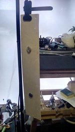
The first picture on the left is one of the side strips ,it's only about 3. 5 inches wide and manages to get down to 400hz or 500hz depending on weights .
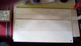
The second picture is two of the strips glued together to match the width of the single panel.
I have not listened to this as yet, but am toying with the idea of gluing on the third strip to make a 10inch by 17 inch panel as in the third picture.
It will be interesting to see how this affects the sound.
Steve.
Attachments

Hello Eric,
Yes the microphone was 1.5 meters away and the microphone was perpendicular to the panel.
I will make some more measurements setting the signal level to 2.8 volts to apply 1W electrical to the 4 ohm exciter.
The measurements I posted the electrical input was 1/4 watt. Looking forward to seeing your data...
Hello Christian,
I am wanting to explore the time domain and not the frequency domain as I want to understand how well the panel replicate the electrical waveform.
Have to come up with a method to check the time response of the microphone as I think the response the the square wave is showing both the microphone and the panel response. The panel response time signature does not follow the electrical signal very well and shows a more sine response rather than a step response. There is ringing in the acoustic waveform that is not present in the electrical signal and the waveform also shows a much slower rise and fall time which I am attributing to the mass of the panel good old F=ma
Cheers,
Steve
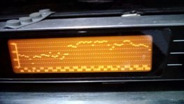
I've been playing some music on the low quality ply panels and thought it was interesting to mention that even though the plots show a fall off below 250hz .
when playing music with the microphone at 3m there is a mutual linking of the panels below the 250hz point .
as can be seen in this photo, the hump in response between 250hz and about 3k is the vocals and guitar.
but below this there is a half decent response down to 40hz which is easily heard.
yes it sounds thin ,but not as much as expected from individual pink noise plots.
I just stuck the exciter on the two strips panel with double sided tape for quick testing.
I think I will glue another strip on now , and do some more listening tomorrow.
Steve.
Attachments
Hello SteveHello Eric,
Yes the microphone was 1.5 meters away and the microphone was perpendicular to the panel.
I will make some more measurements setting the signal level to 2.8 volts to apply 1W electrical to the 4 ohm exciter.
The measurements I posted the electrical input was 1/4 watt. Looking forward to seeing your data...
Hello Christian,
I am wanting to explore the time domain and not the frequency domain as I want to understand how well the panel replicate the electrical waveform.
Have to come up with a method to check the time response of the microphone as I think the response the the square wave is showing both the microphone and the panel response. The panel response time signature does not follow the electrical signal very well and shows a more sine response rather than a step response. There is ringing in the acoustic waveform that is not present in the electrical signal and the waveform also shows a much slower rise and fall time which I am attributing to the mass of the panel good old F=ma
Cheers,
Steve
I am not sure it will be easy to have an analysis from the waveform in its time representation. One reason is the square wave has low spectral content (only odd harmonics, for a 500Hz square wave, 15500Hz which is the 31st harmonic is at about -30dB), so if the harmonic falls into a dip of the panel FR or because of reflection, it might be strongly attenuated. An other reason is that the waveform is the result of the relative phase of its components. If a component is slightly delayed, the waveform will change.
As it seems easy to do this tests, I will try it in a next test cession.
About the role of the mass, I think we have already exchange about it. The extension of the FR to the HF is the proof there is no basic problem of acceleration. The voice coil doesn't have to push against the whole mass of the panel (which is a pistonic model) but "only" a small amount of material just in front of it.
Christian
Christian,I agree on the "theoretical" interest of elongated rectangle. My question is just "Which evidence do we have from a working design?"
Here are some examples of several (in my opinion) working designs of elongated rectangles.
The first two are both the exact same 14"x 48" (3.4 aspect ratio)"Triply" 5.4 mm 5-ply plywood panel with different widths of mounting tape on the perimeter.
The next two are two other similar sized 5 mm 5-ply plywoods. All four sound similar, but I like the HD Birch best, because it is the lowest density, and highest efficiency of them, although that's not obvious in the FR plot. Probably the volume setting was different. But when played side by side the HD Birch is loudest by a few dB. HD just means "Home Depot", and I'm pretty sure only the skin layers are birch (if that!) otherwise it would be much heavier.
The last is 11" x 48" (4.4 aspect ratio) 14mm thick Owens Corning Foamular XPS (the pink stuff). Of course this is maybe 10 dB louder than the plywoods, but falls off a bit more at both ends of the spectrum. As you know, I'm not normally a fan of XPS, but this one actually sounds pretty good. The best of any XPS panel that I've ever built for sure.
All are using a very sturdy frame and 3M double sided mounting tapes (3M Extreme or similar) around most of the perimeter. I leave about 2 to 3 inches free at each corner. Not because I think it makes a difference (I don't think it does), but rather so I can remove the panel from the frame without destroying the panel in the process.
No EQ on any of these.
Eric


Me too! Christian keeps us hopping! 🙂I'm having difficulty keeping up with one day's posts, still less reading the literature and the previous discussions, still less starting on new experiments. 🙁
Paul,Note in searching its better to use "corner modes" ..
Paul
Thanks for those links regarding "corner and edge" modes. I'm surprised now that I never noticed that terminology before! Based on the descriptions, I'm pretty sure they are indeed the same as the "odd,odd" modes.
Funny, though, I never though of them as radiating from the edges or corners. I've always imagined it as the "central pole" being the uncancelled one, and hence thought of them as radiating from the center rather than the edges (or corners). Apparently that's an unpopular viewpoint (and probably wrong too!).
Eric
And have you already tested the method BurntCoil suggested?... or even understood how to proceed?I have thought about buying Sorbothane many times, but never did.
Eric
It seems close to that :
From 6 moons audio Podium & review :
..." Although the size of the vibrating element (panel), density, surface tension and a few other factors affect the bass extension, that is not really what you are asking. The proper answer is in relation to the sound-bridge parts of the loudspeaker. As you saw [while Shelley was doing the repair job on one speaker], I use a high-quality, completely inert, partially rigid rubber to hold the panel in particular places. And if one looks at the loudspeaker with light behind it, one will see some strange dark spots on the sides, which are not aligned with each other and seem to have no relationship with each other at all. But the placement of these sound bridges is absolutely critical and crucial to the bass extension. By adding these to the design, I can alter flaws in the frequency response, sometimes by in excess of a (perceived) 14dB
As you can imagine, the placement of these sound bridges is what takes so much time in the design and cannot really be measured. This is where I will do the design many times until I find an arrangement which is both simple and effective. You may be interested to know that I have a design for a Podium 1 which uses a very large number of sound bridges and absolutely no built-in electronics."...
Thank you for those "evidences" Eric. Excellent bandwidth!Christian,
Here are some examples of several (in my opinion) working designs of elongated rectangles.
The first two are both the exact same 14"x 48" (3.4 aspect ratio)"Triply" 5.4 mm 5-ply plywood panel with different widths of mounting tape on the perimeter.
The next two are two other similar sized 5 mm 5-ply plywoods. All four sound similar, but I like the HD Birch best, because it is the lowest density, and highest efficiency of them, although that's not obvious in the FR plot. Probably the volume setting was different. But when played side by side the HD Birch is loudest by a few dB. HD just means "Home Depot", and I'm pretty sure only the skin layers are birch (if that!) otherwise it would be much heavier.
The last is 11" x 48" (4.4 aspect ratio) 14mm thick Owens Corning Foamular XPS (the pink stuff). Of course this is maybe 10 dB louder than the plywoods, but falls off a bit more at both ends of the spectrum. As you know, I'm not normally a fan of XPS, but this one actually sounds pretty good. The best of any XPS panel that I've ever built for sure.
All are using a very sturdy frame and 3M double sided mounting tapes (3M Extreme or similar) around most of the perimeter. I leave about 2 to 3 inches free at each corner. Not because I think it makes a difference (I don't think it does), but rather so I can remove the panel from the frame without destroying the panel in the process.
No EQ on any of these.
Eric
View attachment 1045921
View attachment 1045922
View attachment 1045923
Not having foam at the corners might be a good idea. I made tests with a 20x30cm XPS 9mm panel. The results where better without foam at the corner and probably even better after rounding them. Nothing says the plywood behaves exactly the same.
Christian
Yes the odd modes survive better. Some of the central antinode also survives due to damping, or if it's over the exciter bc it would be larger to begin with. It would be interesting to calculate with these formulas and see if they do indeed model a DML response below fc.Paul,
Thanks for those links regarding "corner and edge" modes. I'm surprised now that I never noticed that terminology before! Based on the descriptions, I'm pretty sure they are indeed the same as the "odd,odd" modes.
Funny, though, I never though of them as radiating from the edges or corners. I've always imagined it as the "central pole" being the uncancelled one, and hence thought of them as radiating from the center rather than the edges (or corners). Apparently that's an unpopular viewpoint (and probably wrong too!).
Eric
- Home
- Loudspeakers
- Full Range
- A Study of DMLs as a Full Range Speaker