How about Gorilla glue? I think it is polyurethane and frequently used for laminating veneers to substrates if I am not mistaken.Now the next problem is to laminate 0.5mm veneer onto EPS. That's a very serious PIA: Cold glue will not cure in a laminate press (no airflow). Solvent glue eats the EPS. Water-based PVA makes the veneer expand and wrinkle. Epoxy resin leaks through the veneer and sticks to the press itself, but it's too heavy anyway and doubles the weight of the panel. Contact cement either eats the EPS or it makes bubbles under the veneer.
Eric

Your famous compound... that I don't understand how it works!One of my very first experiments was a polycarb disc (100mm dia) mounted by "legs" of hot glue, in a 20mm EPS-paper-skinned panel.

Got a very nice result too.

I think it might be working on the same principles as your ortho-planar design?
What are the blue and red traces?
Just a short one... Exciters with typically 3 or 4 "arms" - are these in general inferior?
//
//
Jamie,thin aluminium, thin acrylic, glass all have good SPL in the 14khz-17khz area, but it's like a huge spike, and i am looking for the right sandwich composite , and panel size to get there. (i.e: needs to be about 16cm of glass if i want a quarter of a wavelength of 7khz to fit within it, according to https://www.omnicalculator.com/physics/sound-wavelength)
Can you explain why it is your goal to have "a quarter of a wavelength of 7khz to fit within it"? I'm not following you. Also, be careful, is it the wavelength of the bending wave of the panel that you are really interested in, or of the sound wave in the air? The two are very different in general.
Eric
Red and blue were right and left speakers. I'd built two of them. I think the one used slightly more glue to stick the paper to the EPS, but I don't remember which is which. I'll have to go back to my notes.Your famous compound... that I don't understand how it works!
What are the blue and red traces?
This is what tripped me up a few times too. I ws trying to nail down a persistent peak in response on a panel, but no matter what driver I used, and no matter where I placed it on the panel, I got the same peak (around 3 or 4k.)... is it the wavelength of the bending wave of the panel that you are really interested in, or of the sound wave in the air? The two are very different in general.
Eric
It turned out to be panel dimensions. A slightly different panel size in the same material gave me a slightly different peak.
Different materials have different internal speeds of sound. Combine this with the natural baffle diffraction (but does this apply to DML's? Prolly not) and you have a whole new circus with many new monkeys.
Those arms are there simply to support the magnet so it does not end up rubbing on the voice coil after long usage. They make no difference whatsoever to the sound despite what some golden-eared listeners might tell you.Just a short one... Exciters with typically 3 or 4 "arms" - are these in general inferior?
You can cut them off if you stick or screw the magnet to a support.
I wouldnt say they are inferior but they WILL CHANGE the way the panel sounds. Anything touching the panel diaphragm except for the exciters voice coil will interfere with the vibrations running through the panel. Its no different then adding damping/weights to a panel as it will change the way it sounds.Just a short one... Exciters with typically 3 or 4 "arms" - are these in general inferior?
//
You can just see for yourself and compare one with the legs and one without and see if you can hear the difference and or which one you prefer better.
If you cant hear the difference then you can just build PA DML's. 😆
Why I'm asking is that I would like too mount exciters in 15, 30 and 45 degres. I'd expect that an unsupported magnet would tilt the coil in the gap - that would be worse than the arms I suppose. Arms hopefully keep coil centred in gap irrespectively of angle...?
But perhaps back support would be the best here?
//
But perhaps back support would be the best here?
//
I think it absolutely is doing the same thing, based on the papers I just read on mechanical band gap design.One of my very first experiments was a polycarb disc (100mm dia) mounted by "legs" of hot glue, in a 20mm EPS-paper-skinned panel.
View attachment 1172642
Got a very nice result too.
View attachment 1172644
I think it might be working on the same principles as your ortho-planar design?
The ortho-planar spring is the panel cut to provide a disc with the damping over the legs, in yours it is the elastic glue.
The reason i chose the spring shape originally, was because I wanted to use a nice looking hardwood, and keep it all as a single piece, but theres no reason that any viscoelastic material can be used as the damping.
this paper shows how it works...
https://arxiv.org/pdf/2108.06171.pdf
It depends! Some are better than others. The 4 arm 40w bass shaker with quad arms is good.Just a short one... Exciters with typically 3 or 4 "arms" - are these in general inferior?
//
The others are all lower rated.
Most of the time the arms are great for permanent attachment to a surface.
But the arms come from the top of the exciter so they move opposite to the foot which sucks.
but the arms are actually on flexible springs which allows it to move without affecting the surface significantly, which is good.
So depending on what your panel is, having arms might make your life easier.
I have two 6x12x1 inch fiberglass coated honeycomb cardboard panels (which I love) mounted on my wall using a Z bracket (like what you use to hold a solar panel off of the roof surface).
On those I’m using dual tri-arm exciters in series since I need it to hold on to the cardboard surface on the back and not dangle at an angle like unsupported ones often do.
For what it's worth, I simply placed a flap of felt over the vented motorHi Eucy,
Yes they are. From my different tests (plywood or PP), it is clear the hump comes from the rear. Some resonance in the venting path (volume, section change...) is a good candidate for explanation. A specific test should prove it (or discard) the hypothesis.
Christian
Eucy
The panel itself.Jamie,
Can you explain why it is your goal to have "a quarter of a wavelength of 7khz to fit within it"? I'm not following you. Also, be careful, is it the wavelength of the bending wave of the panel that you are really interested in, or of the sound wave in the air? The two are very different in general.
Eric
I wanted to see if i could cause amplification instead of attenuation by getting the waves to bounce back on themselves from the edge at different lengths.
It’s a fool’s errand I’m sure but I have the stuff here so I thought I’d give it a shot.
Additionally, in good news. One of the materials I have is super lightweight aluminum foam, and I just tested it.
It totally rocks for frequencies from 1900hz to 18000hz, my 3 way filter I’m using is 1000hz/5000hz crossover.
Thanks for the link, that's a new article for me.Yes! damping the sides smooths the frequency response out, see images below.
If you are interested in damping, you may like this post/thread. It's all about the effect of perimeter damping and methods of assessing the damping properties of various perimeter materials. So far my favorites are EPDM and Poron 92. I haven't tested neoprene yet, but if I can find an inexpensive source I will.
Eric
https://www.diyaudio.com/community/...ing-of-dml-speaker-panels.394465/post-7258557
I'm still not 100% sure I understand your thinking, but I'm also not so sure it's a fool's errand.The panel itself.
I wanted to see if i could cause amplification instead of attenuation by getting the waves to bounce back on themselves from the edge at different lengths.
It’s a fool’s errand I’m sure but I have the stuff here so I thought I’d give it a shot.
First, though, I don't think that calculator is what you want. The calculator is based on longitudinal pressure waves, but those are not the waves that produce sound in a plate. The waves that produce sound in a plate are the transverse bending waves, that (unlike longitudinal waves) are a function of plate thickness and frequency.
If what you want is to create a resonance in the plate at around 7000 Hz, you can do that by sizing the plate correctly. I did a quick FEA model of a 3 mm thick glass plate (simple supports) and it gives the 1,3 mode at 7000 Hz with lateral plate dimensions of about 78 x 107 mm, for example.
But you don't need FEA to get this result, there is an analytical solution here for the modal frequencies of a simply supported plate:
https://www.comsol.com/multiphysics/eigenfrequency-analysis
look for the section titled "Plates" around 2/3 of the way down the page.
Eric
I spotted this article on line yesterday,and at the bottom of the article there is some laser graphs showing a distribted mode panel .
If you look you can see the pistonic area in front of the exciter coil.
But what I found interesting was the cross shape caused by the first direct reflections to the exciter.
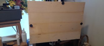
If you look at my photo you can see my crate ply panels with the weights I use to prevent exciter/panel noise, which for some reason was very bad on this panel material?
It also helped to fill in the low frequency dips for better low frequency performance.
Is this a coincidence that I chose these positions for best sound ?
These points would also make good points for mounting the panel ,two for the price of one.
I will leave you to debate, if you are interested.
Steve
https://www.google.com/url?sa=t&sou...FBAWegQIDBAB&usg=AOvVaw0v7Ypw8GcVeVwEydjurIlQ
If you look you can see the pistonic area in front of the exciter coil.
But what I found interesting was the cross shape caused by the first direct reflections to the exciter.
If you look at my photo you can see my crate ply panels with the weights I use to prevent exciter/panel noise, which for some reason was very bad on this panel material?
It also helped to fill in the low frequency dips for better low frequency performance.
Is this a coincidence that I chose these positions for best sound ?
These points would also make good points for mounting the panel ,two for the price of one.
I will leave you to debate, if you are interested.
Steve
https://www.google.com/url?sa=t&sou...FBAWegQIDBAB&usg=AOvVaw0v7Ypw8GcVeVwEydjurIlQ
Attachments
Hi AndreGot a very nice result too.
View attachment 1172644
I think it might be working on the same principles as your ortho-planar design?
Your REW curve should have been adjusted by EQ, right?
Then I also recently tested some measurements
But I found that there are several ways to measure
Which one are you using ("20~20K", "White Noise"...etc)
Can you post your EQ for reference?
Because I found that the EQ of DML seems to be adjusted to extremes, right?
Hi ChristianHello André,
My understanding of how REW works is a bit different. The basis is from the work of M Farina who shown that a recording of a logsweep which is then convoluted with a specific complementary signal gives the IR with a high signal to noise ratio (ratio depending of the duration of the sweep). In a loop back, the electrical signal is directly sent to a second input. This IR is used as time reference.
Christian
Do you mean that ("20~20K", "White Noise"...etc)?
It has the advantage of simplicity and not adding parts and weight. Which dimension is your flap?For what it's worth, I simply placed a flap of felt over the vented motor
Eucy
Christian
HelloDo you mean that ("20~20K", "White Noise"...etc)?
Not sure to understand your question.
Here are some links about the logsweep :
impulse response measurements by sine sweeps look at the 1st slides
Calculating the inverse filter for the (exponential) sine sweep Method, more math and code...
No Sir, no EQ.Your REW curve should have been adjusted by EQ, right?
Then I also recently tested some measurements
But I found that there are several ways to measure
Which one are you using ("20~20K", "White Noise"...etc)
That's a standard log sweep, not white or pink or any other color noise.
Maybe you're talking about weighting?
But if you want to get picky, then you would use REW's RTA function, synchronize it to the generator, and use full spectrum white noise. Just smooth the RTA to the same smoothing that you use in the sweep measurements, and you can do instantaneous spectral analysis on the fly... Great for finding optimal driver positions.
- Home
- Loudspeakers
- Full Range
- A Study of DMLs as a Full Range Speaker