Thanks for collecting highlights from the whole long thread and pointers for easily accessing the info from the thread for reference. May be it would be helpful to have a reference or pointer to this in the first post of the thread for easy access/reference to these important info from the long thread.Hello all,
After the satisfaction of a first pair of plywood panel, I restarted deep diving in this thread, taking new notes. You will find in the attached file links and information about it. It is not for sure an academic objective synthesis but if like me you are looking for reference realizations or the time period or page rank for a post, it may have a utility. If not, not a problem... Additional information, suggestion for reference realizations or posts are welcome. I can post the original open office file if needed.
Christian
Christian,After the satisfaction of a first pair of plywood panel, I restarted deep diving in this thread, taking new notes.....
Thanks for this. Especially interesting how the post rate shot up.
Regarding my plywood DMLs, there are more details in posts 838 to 848, when I first made them, if you want to fill in some of the blanks in your table.
I must admit the frequency response I posted is a bit dubious. I think it must have been a close range measurement, to have gotten so much base. I've done many new measures of them recently at about 1 meter, and the bass falls off rapidly below about 200 Hz. But that's fine, as I use a sub like most people do with their DMLs.
Eric
- Up to now I made panels with a width of at least 40cm and a height from 60 to 125cm. For each, there was a loss in the bass when I measure at the listening position compare to the proximity measurement (few cm in the exciter axis).
Christian,
One reason for your observation may be this: Below the Fc (coincidence frequency) of the panel, sound waves emanating from a DML panel are so called "evanescent waves" that decay rapidly with distance from the panel.
Fc is determined by the stiffness and areal density of the panel. Using a stiffer and/or lighter panel will decrease the Fc, so that the transition from plane waves (that radiate far) and evanescent waves (that decay rapidly) is at a lower frequency. This is one of the reasons that stiff, light panels make good DMLs.
The downside is that stiffer, lighter panels need to be bigger to have the same fundamental frequency (F0) as heavier, flimsier panels.
Here's a cool link from a professor at my alma mater, demonstrating evanescent waves.
https://www.acs.psu.edu/drussell/demos/evanescentwaves/evanescentwaves.html
Eric
Thank you for your reply Eric. The information of your posts are added in the attached version of the file. Seeing again your pictures remind me my first reaction : very clean realization, very nice object.
In a (possible) next update, I will try to sort the panel tables in the order of the posts... honor to the pioneers!
My first idea was to edit the post to update the file (avoiding to create a new post) but I wasn't able today to find the way to do it. Is it possible to edit, modify a published post?
Christian
Attachments
Thank you Eric. It will be probably a reading for after Christmas now. I have been wondering since I started with DML which value to adopt for the coincidence frequency. F0 is easy to understand, the role of Fc on the system quality not so... I don't think it is the reason of the bass drop as I observe it in room and not when the same panel is outside (see #4139). It is with a 3mm plywood panel. I had a similar behavior with a 20mm thick XPS panel (60x125cm) and if I understand you have also a bass fall under 200Hz with a similar material (thicker one). In addition, the evaluation of Fc is more some kHz than hundreds. Saying that, I tried some measurements to visualise the wave speed in the panel with no success. Never the less the question of the coincidence frequency remains. I don't really worry about the bass.. the physics is so the DML are not suitable for bass reproduction; a woofer will be added a day or another. It is more a question of curiosity and learning : those panel can cover a wide frequency range quiet easily but behave strangely (effect of my ignorance) in the bass! I have no experience with OB (Open Baffle) but I wonder in which way a DML is similar. Somewhere I read it is a self-baffle speaker which makes sense.Christian,
One reason for your observation may be this: Below the Fc (coincidence frequency) of the panel, sound waves emanating from a DML panel are so called "evanescent waves" that decay rapidly with distance from the panel.
Fc is determined by the stiffness and areal density of the panel. Using a stiffer and/or lighter panel will decrease the Fc, so that the transition from plane waves (that radiate far) and evanescent waves (that decay rapidly) is at a lower frequency. This is one of the reasons that stiff, light panels make good DMLs.
The downside is that stiffer, lighter panels need to be bigger to have the same fundamental frequency (F0) as heavier, flimsier panels.
Here's a cool link from a professor at my alma mater, demonstrating evanescent waves.
https://www.acs.psu.edu/drussell/demos/evanescentwaves/evanescentwaves.html
Eric
Completely different : could you tell me what is a "FAST system"? this is mention in different posts but I wasn't able to find a definition...(to many posts?)
Merry Christmas and happy new year to all
Christian
Hello CheapvegaProbably not the place to ask, so maybe talk me out of it.
I have 4 downfiring ceiling hung panels and a sub. The panels go from about ~300Hz up to about 11KHz, then need heavy DSP lifting to cover the rest up top. They do sound great though.
I know this kind of goes against everything this thread is about................... but I get bored and like to switch things up a bit. And you guys understand DML magic so you know where I'm coming from to a degree. I wanted to experiment with different materials and all that but I just don't have the time........ looking for something I don't have to think about.
I am sorry not having time right now to think more about what you mentioned but I feel there is a link between your question and the exchanges about low frequencies in my previous post.
Would you mind to give more details about your panels, how they are arranged (or simply remind the post where they are described)? See the file in #4144 for type of questions...
How do you come to the 300hz value?
Same for the 11kHz? Which exciter do you have?
I won't surely say my understanding of the magic of the DML is sufficient to answer but let's try to go a step forward.
Christian
@homeswinghome,
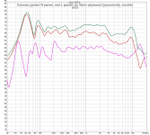
Below is the only chart I have (I don't have one with a measure of the panels alone). The highlighted one is the raw measurement. You can see the dip at 250Hz where the sub falls off and the panel begins to pick up. You can also see the huge falloff up top. I just remembered I put the exciters (Aiyima 25W, 2x per panel in parallel IIRC) on with thick double sided tape which might be robbing some high end response. I will glue them on directly and see if that helps.
I have the panels down hung about 4" off my kitchen ceiling. That probably doesn't help, but that's how I have to hang them lol. I'm sure if I had them perfectly placed I'd get better response, but we work with what we get.

Christian.
on page 206 post 4107 i showed a link to the NXT RUBBISH site I used to be on,I have posted this many times so will not be posting it again.
but it will hopefully answer some of your questions ?
If you tap on to uploaded pictures it should take you to more of my pictures of the response of the panel ,near field and in room ,with my remedy to the problem.
you can also see other panels i have tested.
Hope this helps.
As for the word fast , I usually associate this term to mean something like comparing a horn speaker to say an infinite baffle with heavily doped cones.
I would expect the horn speaker to have quite a lively dynamic sound.
And the infinite baffle to have quite a soft smooth sound ,not so dynamic,sluggish even.
one will make me want to get up and dance,the other will make me to go sleep!
Others I'm sure will put it a lot better or differently than me, but that is how I interpret a fast speakers meaning.
Steve.
Christian.
normally I would not recommend mounting an exciter centrally on a free edged dml panel.
But the canvas art panel is a different beast.
the centrally mounted exciter and ply on the canvas helps balance the panel for pistonic motion.
also the canvas helps dampen a little and disperse the edge reflections (I believe).
So that the edge reflections are not a destructive problem similar to the affect of the roll surround on a cone speaker.
The only other thing I was going to try do was apply my fabric dome in the centre of the exciter coil area.
I think this would have made a good improvement (maybe) but I never quite got around to it.
I'm always getting distracted.
Steve.
Christian.
I have posted many pictures , recordings and measurements on this forum ,I know it is hard to find them ,but they are buried here somewhere .
I thought the recordings would be good as everyone can hear and make up their own mind about free floating dml panels ,large small ,different shapes and materials.
I think the recordings sound pretty good considering,using my methods,and have them on my tablet ,which I take away with me on holiday for general music listening with headphones.
Steve
Christian,I tried some measurements to visualise the wave speed in the panel with no success.
Completely different : could you tell me what is a "FAST system"? this is mention in different posts but I wasn't able to find a definition...(to many posts?)
What measurements did you try to visualize wave speed? Even though you said you had no success, I'm curious what exactly you tried.
Regarding "FAST", it simply means combining a full range speaker with a subwoofer. I can't say for sure what the acronym is supposed to stand for, but I've seen Full range ASsist Technology as one possible explanation, but that may not be correct. But in any event it's the same as WAW, or Woofer Assisted Wideband.
Eric
Thank you for the acronyms Eric. So FAST or WAW system are what I do.Christian,
What measurements did you try to visualize wave speed? Even though you said you had no success, I'm curious what exactly you tried.
For the wave speed tentative of measurements :
- In alternative to umik1 USB microphone I use a hand recorder Zoom H1n with 2 omni electret PUIaudio AOM5024 (the reason of the AOM5024 is their much better signal to noise ratio than other electret, they are affordable, easy to find - ie Mouser)
- with that I have a logsweep on a usb stick
- The Zoom H1n allow me to record 2 synchronized signals
- For the wave speed test, one mic is at the exciter axis, 1 or 2cm from the membrane
- The second mic is placed in a second location, 20, 40, 60cm from the axis in the panel plan, at the same distance from the membrane than the 1st one.
- The sweep is recorded, a correlation extracts the Impulse response.
- Some home made Python scripts make all of that a little bit easier but the core is the use of logsweep and correlation from DRC by Denis Sbragion http://drc-fir.sourceforge.net/ (my laptop is under Linux). See below my notes about Denis's tool (those notes should end with may others in a web site but it needs time..)
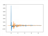
- Attached is an exemple on my plywood panel showing the IR at the exciter (blue) and 40 cm away (orange)
- I applied bandpass filtering in order to have a delay versus frequency and check against the theory...
- At least, we can see how is the attenuation as the distance from the exciter increase
- This try was based on the hypothesis the second mic picks up the sound coming from the panel in front of it. Is it so sure?
Christian
Attachments
@homeswinghome
Below is the only chart I have (I don't have one with a measure of the panels alone). The highlighted one is the raw measurement. You can see the dip at 250Hz where the sub falls off and the panel begins to pick up. You can also see the huge falloff up top. I just remembered I put the exciters (Aiyima 25W, 2x per panel in parallel IIRC) on with thick double sided tape which might be robbing some high end response. I will glue them on directly and see if that helps.
I have the panels down hung about 4" off my kitchen ceiling. That probably doesn't help, but that's how I have to hang them lol. I'm sure if I had them perfectly placed I'd get better response, but we work with what we get.
Hello Cheapvega,
DMLs are in the same family than OB or other panels : the back is opened, the wave from the back bounces on the wall behind the panel and comes back. The standard recommendation is to have 1m free behind... which is often not possible. In your case you are even below the 30cm with something like 10cm. It is what Robixxx1 answered to your question in an other thread. It might be reason of the peak at 400Hz. For the hole at 300Hz, I think more investigations are needed. At least a measurement without the sub and perhaps in several listening points.
For sure , there are several elements in your design that make it challenging :
- the low distance to the ceiling
- the square shape of the panels (high symmetry concentrates the problem in few frequencies)
- two exciters. One can expect effects on the treble
So I don't think you won't have better results with OB. The way seems in the understanding of the effect of the room boundaries and perhaps the interactions between the panels (you said 4?).
Why 4 panels instead of 2 lager one? Some in other posts seem happy to have left and right exciters on the same physical panel which make sense thinking about DML : the membrane and the baffle are the same part.
Christian
Magic sponges are white melamine foam, commonly referred to as "magic erasers". XRK971 recommends these to line speaker boxes. You can get a bag of 50 from China on the internet for about $6-8. Look under melamine sponge. That is what I have, in addition to drapes, between my DMLs and the window, about 10" away. I believe I get excellent sound reproduction. They come as a 10x6x2 rectangle. I glued them together to make 2 panels. I would mount them on a piece of card stock, as they don't stay glued together very well edge-glued (with the glue I used). Spray adhesive should work very well.
Christian --
Except... DMLs produce front and back waves in-phase.
All (well at least most) other OB and panel drivers produce front and back waves out-of-phase.
Such out of phase drivers need distance from a wall behind them to prevent the back wave from canceling the front wave.
One can place out-of-phase dipoles right against a back wall to limit cancellation but this can introduce other issues.
DML's play like instruments -- in-phase and omnidirectional -- distinguishing DMLs from perhaps all other types of dipole drivers.
Instruments may sound best away from a back wall in any given room, but they don't have out of phase back wave that would cancel a front wave.
I find DMLs far more able to sound very good much closer to a back wall than any other type of dipole speaker I've ever had in my home (and I've had a lot of of them ;-)
DMLs are in the same family than OB or other panels : the back is opened, the wave from the back bounces on the wall behind the panel and comes back. The standard recommendation is to have 1m free behind... which is often not possible. In your case you are even below the 30cm with something like 10cm.
Except... DMLs produce front and back waves in-phase.
All (well at least most) other OB and panel drivers produce front and back waves out-of-phase.
Such out of phase drivers need distance from a wall behind them to prevent the back wave from canceling the front wave.
One can place out-of-phase dipoles right against a back wall to limit cancellation but this can introduce other issues.
DML's play like instruments -- in-phase and omnidirectional -- distinguishing DMLs from perhaps all other types of dipole drivers.
Instruments may sound best away from a back wall in any given room, but they don't have out of phase back wave that would cancel a front wave.
I find DMLs far more able to sound very good much closer to a back wall than any other type of dipole speaker I've ever had in my home (and I've had a lot of of them ;-)
@spedge : Thank you for the feedback. Before building panels, I read many posts including yours in audiocircle... the difficulty is to remember what was explained. In addition in a first reading I had a certain focus which is different now. Any way, I (at least I think) follow the "construction plan" for canvas panel. Here in France, the canvas are 41x33cm. The pad and the exciter are at the center (fully agree with you about the mechanical balance). As I had no balsa plywood at hand, I first tried to cut and shape a 3mm light plywood... In fact it was light until I put in on the balance.. 14g. I was afraid by it and finally glued 2 layers from a 1mm balsa board, at 90°.
@aagas : the phase relation between the front and the back is a question that puzzles my engineer's brain. I still not understand how they can be in phase... I remember tough (endless?) exchanges about that in past posts (here or in audiocircle... can't remember) and I wouldn't re-open a kind of Pandora's box! For the rest, I have not the experience you have with many different speakers but I fully agree the DML have this capacity to sound very good in a room. Many other DML builders coming from other type of loudspeakers said similar thinks.
To come back to the my 1st canvas test you will find below some measurements.
I made the choice of the IEC2623 export option from REW.
There is no EQ, no woofer. Only the panel. All the measures are with an Umik1 and REW.
The canvas have an incredible sound, time, cost efficiency score. For a low spending, quite quickly you can set up a pair of very good speakers! Cherry on the top of the cake : their size.
For now the missing point I noted compare to the plywood panel is the lack of very fast transients (or is it an excess from the plywood?)
What is noticable from the FR, is the damping in the canvas is higher (lower Q) so gap between the resonance is more easily fills.
Does somebody has advice/comment about :
Christian
@aagas : the phase relation between the front and the back is a question that puzzles my engineer's brain. I still not understand how they can be in phase... I remember tough (endless?) exchanges about that in past posts (here or in audiocircle... can't remember) and I wouldn't re-open a kind of Pandora's box! For the rest, I have not the experience you have with many different speakers but I fully agree the DML have this capacity to sound very good in a room. Many other DML builders coming from other type of loudspeakers said similar thinks.
To come back to the my 1st canvas test you will find below some measurements.
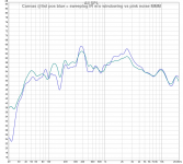
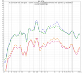
- proximity versus listening position
- comparison to 3mm plywood (be careful it is not in the same room)
- IR logsweep compared to pink noise MMM (Moving Microphone Measurement) - the results are similar
I made the choice of the IEC2623 export option from REW.
There is no EQ, no woofer. Only the panel. All the measures are with an Umik1 and REW.
The canvas have an incredible sound, time, cost efficiency score. For a low spending, quite quickly you can set up a pair of very good speakers! Cherry on the top of the cake : their size.
For now the missing point I noted compare to the plywood panel is the lack of very fast transients (or is it an excess from the plywood?)
What is noticable from the FR, is the damping in the canvas is higher (lower Q) so gap between the resonance is more easily fills.
Does somebody has advice/comment about :
- this difference in transient? Is it written somewhere in the FR?
- the FR shows peaks in medium (200, 400Hz and after). Those peaks are not in the proximity FR. Is there a method to search/understand their origin?
Christian
Attachments
For the wave speed tentative of measurements :
Please give me your feedback. I did those tests on a short period last July and after reading Aagas (#3619) about 1st reflections, there is perhaps some interest to undust this.
- In alternative to umik1 USB microphone I use a hand recorder Zoom H1n with 2 omni electret PUIaudio AOM5024 (the reason of the AOM5024 is their much better signal to noise ratio than other electret, they are affordable, easy to find - ie Mouser)
- with that I have a logsweep on a usb stick
- The Zoom H1n allow me to record 2 synchronized signals
- For the wave speed test, one mic is at the exciter axis, 1 or 2cm from the membrane
- The second mic is placed in a second location, 20, 40, 60cm from the axis in the panel plan, at the same distance from the membrane than the 1st one.
- The sweep is recorded, a correlation extracts the Impulse response.
- Some home made Python scripts make all of that a little bit easier but the core is the use of logsweep and correlation from DRC by Denis Sbragion http://drc-fir.sourceforge.net/ (my laptop is under Linux). See below my notes about Denis's tool (those notes should end with may others in a web site but it needs time..)
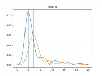
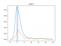
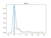
- Attached is an exemple on my plywood panel showing the IR at the exciter (blue) and 40 cm away (orange)
- I applied bandpass filtering in order to have a delay versus frequency and check against the theory...
- At least, we can see how is the attenuation as the distance from the exciter increase
- This try was based on the hypothesis the second mic picks up the sound coming from the panel in front of it. Is it so sure?
Christian
Christian,
Thanks for the description of your measurements. Very interesting.
So, was it your hope to be able to determine the wave speed in the plate by measuring the delay of the peak in the impulse response between the first and second microphone? Is this correct? But then the shape of the impulse was so different at the second microphone that you could not clearly pick out the time delay? Is that why you felt your measurement attempt was unsuccessful?
Actually, I think your measurement may be good. But the "problem" is that the wavespeed of a bending wave in a plate is not a constant, but rather depends on frequency. This is perhaps surprising. For example, the speed of sound waves in air is a constant, independent of frequency. But this is not so for flexural bending waves. Rather they follow the rule:
c=(B/m)^1/4*(W)^1/2
where c is the speed of the wave, B is the plate stiffness, m is the plate areal density, and W is the angular frequency of the wave.
See equation 3.85 from page 55 here, for any clarification:
https://www.google.com/books/editio...pAtwmxs-jaMC?hl=en&gbpv=1&printsec=frontcover
So since an impulse is not a particular frequency, but rather contains a whole spectrum of frequencies, it does not propagate across the plate a a particular speed, rather, each portion of the impulse travels across the plate at a different speed, depending on it's frequency.
As a result, it is actually expected that an impulse will change shape, at is moves, because it spreads out as it moves, since the high frequency components move faster than the low frequency components. Such waves are called dispersive waves. There is some explanation here:
https://www.acs.psu.edu/drussell/Demos/Dispersion/Flexural.html
and here:
https://www.acs.psu.edu/drussell/Demos/Dispersion/dispersion.html
Your impulse measurements look a lot to me like the figure in the first link above titled : "Hammer impact at point 1"
Eric
Hello EricChristian,
Thanks for the description of your measurements. Very interesting.
So, was it your hope to be able to determine the wave speed in the plate by measuring the delay of the peak in the impulse response between the first and second microphone? Is this correct? But then the shape of the impulse was so different at the second microphone that you could not clearly pick out the time delay? Is that why you felt your measurement attempt was unsuccessful?
Actually, I think your measurement may be good. But the "problem" is that the wavespeed of a bending wave in a plate is not a constant, but rather depends on frequency. This is perhaps surprising. For example, the speed of sound waves in air is a constant, independent of frequency. But this is not so for flexural bending waves. Rather they follow the rule:
c=(B/m)^1/4*(W)^1/2
where c is the speed of the wave, B is the plate stiffness, m is the plate areal density, and W is the angular frequency of the wave.
...
I see my explanations were not fully clear and I should have added more pictures.
So :
- yes the basic idea is to measure the delay between the signals of the 2 microphones
- the formula you mention is what I expected by the theory of bending waves in a plate
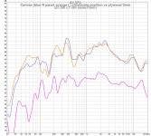
- after having the IR, I apply to them a band-pass filter to limit them in frequency
- it is between the IR band-pass filtered I measure the delay, not between the raw IR which are for sure broadband
- when I plotted the delay as a function of the central frequency of the band pass filter, I didn't get what is expected from the theory but something "erratic".
Something is wrong somewhere.
You will find attached some example of filtered IR. I am sorry not showing for now the delay vs frequency but I am not sure of what my Python script output for now (problem of a software going from modifications to modifications and abandoned a few months ago), I should spend some time to look at it. If you have an interest for more on this topic, I could probably do it. Let me know
Christian
Attachments

- Home
- Loudspeakers
- Full Range
- A Study of DMLs as a Full Range Speaker