Steve,
I ordered blu tack, should come by Wednesday.
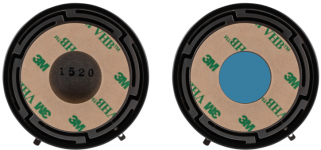
Just to get specific, I've attached photos of the panel side (front surface) of the Dayton Audio DAEX32EP-4 Thruster I use.
The left one, as is out of the box. The right one with the center in blue.
Does the right picture accurately show where you propose I place the blu tack?
I used the suppled 3M VHB (Very High Bond) tape to secure the exciters to the panels.
I've worked with VHB tape before and have experience in preparing surfaces.
Doing so produces a near permanent bond.
Neither of the exciters feel at all like they've come loose.
I think I'd have to figure out a way to slice off the VHB tape to remove them.
Perhaps more likely, if the VHB tape adheres more strongly than the aluminum skin does to the honeycomb core the forces of the exciter might begin to delaminate the panel.
I don't see any evidence of this, but I'll keep my eyes and ears on it.
I hope to get to some measurements this afternoon.
The blutack should be placed on the front surface area in the middle of the voice coil area.
I ordered blu tack, should come by Wednesday.
Just to get specific, I've attached photos of the panel side (front surface) of the Dayton Audio DAEX32EP-4 Thruster I use.
The left one, as is out of the box. The right one with the center in blue.
Does the right picture accurately show where you propose I place the blu tack?
I'd also check that the exciter isn't coming loose,this can cause strange noises and loss of hf,long before the exciter falls off.
If it's held on with sticky tape, put pressure on the exciter to help re-stick it.
I used the suppled 3M VHB (Very High Bond) tape to secure the exciters to the panels.
I've worked with VHB tape before and have experience in preparing surfaces.
Doing so produces a near permanent bond.
Neither of the exciters feel at all like they've come loose.
I think I'd have to figure out a way to slice off the VHB tape to remove them.
Perhaps more likely, if the VHB tape adheres more strongly than the aluminum skin does to the honeycomb core the forces of the exciter might begin to delaminate the panel.
I don't see any evidence of this, but I'll keep my eyes and ears on it.
I hope to get to some measurements this afternoon.
Attachments
Nicolas ojala.
I think my small card or even my small balsa ply panel's would be ideal for surround sound systems.
They can be placed closer to the walls without the problems of larger panels.
No sweet spot to worry about ,better rendition of sound effects.
Hopefully better clarity of spoken voices which can be a problem sometimes,the amount of times I have had to rewind to try and figure out what someone has said😕
As long as you don't try to use them to beam the sound off ceilings or walls as in modern surround systems.
Steve.
Dave,
Did you buy these carbon/nomex panels or make them yourself? I'd be interested to know more details about your panels.
Eric
Eric,
I found a company in China (CA Composites) who made the carbon/Nomex panels for me. The panels are actually 1000hx300wx3.5mm thick. They had a minimum purchase but they were still cheaper than US sources.
Thanks,
Dave
Attachments
aagas.
Yes the blue area in the photo is the internal area of the coil.
You could fill this area to see if it reduces or kills the sound,then if it reduces the sound you can try a smaller piece about the size of a small pea in the very centre of the coil area.
If when measuring you could do one measurement from the exciter side,as this could be quite enlightening,maybe?
Ps.
Looking at your original measurements that had no smoothing,I noticed a dip at about 2.8k which does not show up on the smoothed response? Could this be a sign of something going on?,it looked about 5db maybe? But was hard to tell because of the 20db scale.
Steve.
Steve,
Thanks.
Do you suggest this because you think the internal area of the coil could slam against the panel?
If I follow, I'd leave the microphone in the same place and turn each speaker around.
Not certain if my optical cable and power cords will stretch that far, but I'll give it a try.
The dip at 2.8k looks about 2.3 db.
I'll scale the next measurements I post at 10 db and see what they show.
Yes the blue area in the photo is the internal area of the coil.
Thanks.
You could fill this area to see if it reduces or kills the sound, then if it reduces the sound you can try a smaller piece about the size of a small pea in the very centre of the coil area.
Do you suggest this because you think the internal area of the coil could slam against the panel?
If when measuring you could do one measurement from the exciter side,as this could be quite enlightening,maybe?
If I follow, I'd leave the microphone in the same place and turn each speaker around.
Not certain if my optical cable and power cords will stretch that far, but I'll give it a try.
Looking at your original measurements that had no smoothing,I noticed a dip at about 2.8k which does not show up on the smoothed response? Could this be a sign of something going on?,it looked about 5db maybe? But was hard to tell because of the 20db scale.
The dip at 2.8k looks about 2.3 db.
I'll scale the next measurements I post at 10 db and see what they show.
Eric,
I found a company in China (CA Composites) who made the carbon/Nomex panels for me. The panels are actually 1000hx300wx3.5mm thick. They had a minimum purchase but they were still cheaper than US sources.
Thanks,
Dave
Hello
I was also interested in trying that material with exactly your size, I wanted to ask you how do they sound? could you put an audio shot?
I may have the address of who sold you the panel and costs.
Thank you
aagas.
The frequency response from the exciter at the rear will be modified by the exciter itself causing irregularities.
This Could be reflecting from the rear wall or window?
I usually move the microphone around the back of the exciter to see if anything unusual is picked up in real time,like a sharp peak of dip.
So not necessary to turn the panel around.
You have to trace where the sound is coming from before you can say what is causing it.
You have not said if the sound is just in the recording or is actually coming from the panel?
Please don't start pulling things about it you don't hear any problems.
Steve.
Steve,
I've got an old "Sheffield / A2TB Test Disc - 'My Disc'" on my Mac. I might provide help with the investigation.
More to follow...
I've got an old "Sheffield / A2TB Test Disc - 'My Disc'" on my Mac. I might provide help with the investigation.
More to follow...
Update
Alright, started to set everything up and get used to working with REW, I decided to change and add some things in my test-setup:
circular = green
square = orange
Now, I ll try to find some resources on how to interpret these frequency responses.
Any comments on the changes and additions? 🙂
Hi fellows,
After reading through the whole thread, I am so excited to finally start my own basic testing on OffGridKindaGuy's Canvas DML Design.
I am really grateful about you guys sharing your knowledge and helping me in this process!
Being fairly new to loudspeaker building, I am trying to come up with a test-setup that gives me a basic understanding of core principles, meaningful correlations and data. [...]

Alright, started to set everything up and get used to working with REW, I decided to change and add some things in my test-setup:
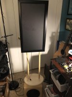
- I mount the Exciter to a wooden Stand with 4mm felt in between. (see pic 1 & 2)
- I decrease the Distance between Mic and Panel down to 50cm. Gated Window = 0.4 - 5.85ms
- I set the AMP Output Voltage to 0.6V which equals right now (dependent on the surface area and thickness) around 81dB SPL at 50cm (= around 90mW?)
- I connect my USB Audio Interface via Cinch to the AMP (removing the Raspbi and DSP)
- displaying the frequency response I use a 50-60dB SPL and 150Hz-20kHz Range
circular = green
square = orange
Now, I ll try to find some resources on how to interpret these frequency responses.
Any comments on the changes and additions? 🙂
Attachments

Hi Bernardy.
You placed the exciter dead in the centre of the panels,not the best place to put them as this will cause a large standing wave,especially with the circular panel.
The green line peaks seam to have taken a jump to the left ? A bit like the rocky horror show😀
Above 12k they look pretty similar.
If doing this I would probably take a measurement at about 2inches in front of the exciter first, to see what the coils are actually putting into the panel,this hopefully should be pretty much full range ?
Steve.
Bernardy,
If I follow your description and your photos, the adhesive connection between your panel and the exciter places the entire weight of the panel on the exciter itself.
(I do wonder if you need the felt between the exciter and the wooden stand. Varying that particular connection could prove interesting.)
I appreciate the simplicity (even elegance) of your design.
I surmise that the lighter the panel, the more ideal such a solution. But panels have weight.
It seems to me that suspending the entire weight of the panel on an exciter would place significant load and stress on the exciter and the exciter's internal components.
Developers of the technology have designed exciters to move/vibrate the panels not to support them. Hence so many projects that suspend/mount panels as well as those that mount the exciters on some kind of supporting structure. Many designs do both.
I could imagine an exciter designed to handle significant panel weights, but certainly don't know of any. Of course I've conducted my experiments in all of this with much larger and heavier panels (71" high x 29" wide) so I haven't made an exhaustive search.
It seems to me that an exciter designed to carry the panel load would have a range of engineering tradeoffs.
All this said, pushing limits and conventions seems like the point of this collaborative thread.
I very much look forward to watching (even hearing) your explorations.
-- Andreas
aagas.
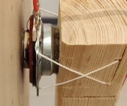
This was one of my test panels,2mm xps.
If the panel is of a similar or less weight it is OK to hang the panel off of the exciter.
(Untitled)
Steve.
This was one of my test panels,2mm xps.
If the panel is of a similar or less weight it is OK to hang the panel off of the exciter.
(Untitled)
Steve.
Teardrop shaped panels
Has anyone tried (or heard of) teardrop-shaped panels, with the exciter at the narrow end?
This makes sense to me because:
* Teardrop shape has very few points where a ray from the exciter meets an edge at 90 degrees, minimising standing waves from exciter to edge
* Similarly, shape has only a couple of points where a line drawn anywhere through the panel meets the two opposite edges at 90 degrees, minimising standing waves from edge to edge
* With the exciter at the narrow end, it provides progressively more surface area for the lower frequencies. This is required because i) more energy to excite lower frequencies and ii) frequencies below the panel critical frequency are radiated less efficiently anyway. This also explains why burntcoil found long panels to have a flatter FR, because exciting lower freqs is overall less efficient, requiring more panel area devoted to low freqs.
* The blunt end provides maximal smoothing for low frequencies arriving from the exciter, because there is a smooth distribution of lengths from the exciter to the various points along this edge. Low freqs are particularly susceptible to peaks, because the wavelength is of the same order of magnitude as the panel dimensions, giving strong isolated resonances where (for example depending upon support method) a panel dimension coincides with a half-wavelength.
* Highest frequencies are clustered close to the exciter anyway, so can be more effectively separately optimised by (eg) different surface treatments or variable thickness.
Good Morning!
Thank you Steve and Andreas for your feedback.
Is there a way to relate the biggest peaks and troughs from the frequency response graph to panel dimensions?
Setup, Thickness and Surface Area being equal, this can just have to do with a mode offset due to the different shape - radius = 12cm vs. 1/2 side = 10.6cm...?
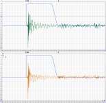
Looking at my Impulse Measurements though, I wonder if using this approach of gated measurements is actually valid since there is clearly no temporal separation between the end of the impulse and the first room reflection... 😕 see the attached graph: circular shape = green, square shape = orange;
So, I think I need to move the mic even closer to the panel to have a longer time window and hope for this separation to appear, as you suggest?
Is this long impulse a trademark of DMLs?
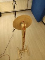
But maybe I try to attach a 'foam coated foot' to the wooden stand on which the panel can rest on so that the voice coil can do its job without interference from gravity.
For the final built I ll definitely attach the exciter to the wooden frame of the canvas.
Thank you Steve and Andreas for your feedback.
I try to standardize the testing, keeping all parameters (including exciter attachment) the same for all measurements. Especially with testing different panel sizes, attaching the exciter in its center seems to be the only way, introducing its shortcomings at least 'evenly' into all the measurements. 🙂 For the final built I ll definitely try to find a better exciter location.spedge said:You placed the exciter dead in the centre of the panels,not the best place to put them as this will cause a large standing wave,especially with the circular panel.
Is there a way to relate the biggest peaks and troughs from the frequency response graph to panel dimensions?
Yeah, strange. What might be an explanation for this?spedge said:The green line peaks seam to have taken a jump to the left ? A bit like the rocky horror show😀
Setup, Thickness and Surface Area being equal, this can just have to do with a mode offset due to the different shape - radius = 12cm vs. 1/2 side = 10.6cm...?
I am fairly new to taking measurements. I thought with using gated measurements I ll just measure the panel-exciter performance without any room interference?spedge said:If doing this I would probably take a measurement at about 2inches in front of the exciter first, to see what the coils are actually putting into the panel,this hopefully should be pretty much full range ?
Steve.
Looking at my Impulse Measurements though, I wonder if using this approach of gated measurements is actually valid since there is clearly no temporal separation between the end of the impulse and the first room reflection... 😕 see the attached graph: circular shape = green, square shape = orange;
So, I think I need to move the mic even closer to the panel to have a longer time window and hope for this separation to appear, as you suggest?
Is this long impulse a trademark of DMLs?
That is a good point. I initially moved away from the idea of clamping the panel in between a wooden frame and foam, to not introduce a variable of different clamping pressure on the panels. Moreover, the panels (except the 6.5mm at 450cm²) are all lighter than the exciter, thinking that mounting the exciter rather than the panel would be the lesser of two evils.aagas said:If I follow your description and your photos, the adhesive connection between your panel and the exciter places the entire weight of the panel on the exciter itself.[...] It seems to me that suspending the entire weight of the panel on an exciter would place significant load and stress on the exciter and the exciter's internal components.
But maybe I try to attach a 'foam coated foot' to the wooden stand on which the panel can rest on so that the voice coil can do its job without interference from gravity.
For the final built I ll definitely attach the exciter to the wooden frame of the canvas.
Attachments
Last edited:
Pway.
You mean like fig3 in this NXT patent?
Notice how they place the exciter in the larger position to better drive the panel.
I believe burntcoil was tapping into the main resonance of the panel to increase the low end,which had a good effect on thin panels.
The spread of hf across the panel depends on the rigidity of the panel and how far you push the panel into dml mode + among other things.
US20060159293A1 - Acoustic device
- Google Patents
Or my heart shaped panels on pages 213 and 215 with pictures and recordings,so you can see and hear how fantastic they are😀😀😀
Steve.

Steve,
Yes it had occurred to me that a teardrop is only using a fraction of the applied energy. I had thought to ameliorate this if need be by 1) a rigid reflector behind the exciter, directing waves back toward the blunt end and ii) simple or clamped support, which seems to increase the SPL significantly at low frequency (less wasted at the edges due to short circuit effect?). Anyway, early days, I have to find time to do more testing first. With clamped or simple support and damping material all around, I hope to see far less resonance, closer to the infinite panel of theory, with travelling waves rather than standing waves. Moving the exciter very close to the teardrop edge should help, because it wont excite the low-order harmonics of the panel - not acting like a vibrating beam, but more sending a stream of waves across the panel to be absorbed on the other send with less reflection.
Yes, that's what Id guessed. It my tests so far, bass is definitely present to quite low freqs, but with large peaks/troughs due to resonance of the free structure.
[QUOTE/]
The spread of hf across the panel depends on the rigidity of the panel and how far you push the panel into dml mode + among other things.
[/QUOTE]
Yes rigidity. Also panel thickness & material damping separately from its contribution to rigidity. The wavelength needs to be at least several times (ideally >>) the thickness of the panel, which is not the case for hf and 30mm XPS, for which fr drops rapidly at ~10k. At hf, the sound is more and more localised near the exciter on the exciter side, and is absorbed by the panel - so mainly near the surface on the exciter side. So need to either make panel thinner whilst keeping same area density and stiffness (thus composites), use something else (like the end of an aluminium can as I saw mentioned) to radiate hf.
By 'pushing into DML mode' are you referring to critical freq of the panel?
I see! Great for Valentines day - a musical greeting card, with actual music! i presume your wife liked them 🙂
You mean like fig3 in this NXT patent?
Notice how they place the exciter in the larger position to better drive the panel.
Yes it had occurred to me that a teardrop is only using a fraction of the applied energy. I had thought to ameliorate this if need be by 1) a rigid reflector behind the exciter, directing waves back toward the blunt end and ii) simple or clamped support, which seems to increase the SPL significantly at low frequency (less wasted at the edges due to short circuit effect?). Anyway, early days, I have to find time to do more testing first. With clamped or simple support and damping material all around, I hope to see far less resonance, closer to the infinite panel of theory, with travelling waves rather than standing waves. Moving the exciter very close to the teardrop edge should help, because it wont excite the low-order harmonics of the panel - not acting like a vibrating beam, but more sending a stream of waves across the panel to be absorbed on the other send with less reflection.
I believe burntcoil was tapping into the main resonance of the panel to increase the low end,which had a good effect on thin panels.
Yes, that's what Id guessed. It my tests so far, bass is definitely present to quite low freqs, but with large peaks/troughs due to resonance of the free structure.
[QUOTE/]
The spread of hf across the panel depends on the rigidity of the panel and how far you push the panel into dml mode + among other things.
[/QUOTE]
Yes rigidity. Also panel thickness & material damping separately from its contribution to rigidity. The wavelength needs to be at least several times (ideally >>) the thickness of the panel, which is not the case for hf and 30mm XPS, for which fr drops rapidly at ~10k. At hf, the sound is more and more localised near the exciter on the exciter side, and is absorbed by the panel - so mainly near the surface on the exciter side. So need to either make panel thinner whilst keeping same area density and stiffness (thus composites), use something else (like the end of an aluminium can as I saw mentioned) to radiate hf.
By 'pushing into DML mode' are you referring to critical freq of the panel?
Or my heart shaped panels on pages 213 and 215 with pictures and recordings,so you can see and hear how fantastic they are😀😀😀
Steve.
I see! Great for Valentines day - a musical greeting card, with actual music! i presume your wife liked them 🙂
I just did some more measurements now up close to the panel and with a little foot for the panel to rest on.
I believe voice coil sag is real ! 😀 but as it turns out, resting the panel on a little foot to keep the panel perfectly vertical and the exciter unstressed, doesn't significantly change the frequency response of the panel. So for this first few measurements I ll leave them hanging.
Shortening the distance between Mic and Panel to around 13cm let me increase the gated Windows but I still don't see any end to the impulse and a clear cut between impulse and first room reflection like on the attached pic's impulse performance on what I believe to be a conventional cone speaker...
Would be interesting to find out what might improve this impulse response of a DML panel. Higher compression/flexural strength? Damping?...
Attachments

Bernardy.
On page 6 there is an explanation of dml impulse responses and why it is ok to have a long tail.
http://www.soundright.org.uk/NXTchaos.pdf
Steve.
On page 6 there is an explanation of dml impulse responses and why it is ok to have a long tail.
http://www.soundright.org.uk/NXTchaos.pdf
Steve.
- Home
- Loudspeakers
- Full Range
- A Study of DMLs as a Full Range Speaker