It won't be wirewound, officially it is a safety component, a fusible type that goes open circuit when overloaded rather than burning and smoking (which can frighten the punters 😉)
Officially it should be one of the same type but lets say for 'test purposes' you can fit a normal carbon or metal film type. If it is hard to get to then you can probably do a neat job just by snipping it out and soldering a new one neatly to the cut off leads.
Officially it should be one of the same type but lets say for 'test purposes' you can fit a normal carbon or metal film type. If it is hard to get to then you can probably do a neat job just by snipping it out and soldering a new one neatly to the cut off leads.
It won't be wirewound, officially it is a safety component, a fusible type that goes open circuit when overloaded rather than burning and smoking (which can frighten the punters 😉)
Ah OK that's good - i'll get the carbon film one then. 😉
May as well order a few more sets of output transistors while i'm at it - they may come in handy in the future (the legs are surely getting weaker as I keep bending them to reach the back of the board - who knows when they might give up) and I need to order a bit more than 6 resistors 😛
Officially it should be one of the same type but lets say for 'test purposes' you can fit a normal carbon or metal film type. If it is hard to get to then you can probably do a neat job just by snipping it out and soldering a new one neatly to the cut off leads.
That's a great idea - unfortunately as I look at it, it's surrounded by tall electrolytic caps and a heatsink in a very narrow spot so I don't think i'll be able to squeeze in from above. I'll just have to remove the entire main board I think, nevermind.
It wasn't so bad to get the main board out after all - I first thought that i'd have to get the torroid out but it turned out not to be the case 😉
access can be a real issue on some units unfortunately.
Hi Mooly 🙂
The parts arrived today - got them fitted and, thanks to your brilliant diagnosis, we are back to where we left off 😉
I tested the +68V at R310 and it measured +66.9V.
Unfortunately I can't really check the -68V right now because the hooked probes I ordered are far to chunky to grab the legs of any of the resistors on that track. I have ordered another set which should be much better but until then I'm too scared to try with the old 'slip prone' needle probes.
I did manage to test the -18V across D302 and it looks good at -17.8V.
Tested across D301 and looks OK too at 17.7V.
So it's just the -68V I haven't managed to check.
The amp is back to behaving exactly as it was before.
Last edited:
I'm pleased it is at least back to how it was. It's a bit scary when something like that happens.
So the 'noise' issue at switch on and off... hmm... I'll give that some more thought. We might have to get a bit creative in trying to diagnose this.
So the 'noise' issue at switch on and off... hmm... I'll give that some more thought. We might have to get a bit creative in trying to diagnose this.

Lol, it's a pretty safe bet that rail will be OK. Just measure it on R316, what could go possibly wrong 😱
I'm pleased it is at least back to how it was. It's a bit scary when something like that happens.
Yes, you're doing a fantastic job or rescuing me! Second time I've caused trouble with the probes. Shows how important it is to use the correct tools for the job. The smaller plunger hooks should fix that. I have to say DigiKey have been really quick to deliver - just a couple of days 🙂
So the 'noise' issue at switch on and off... hmm... I'll give that some more thought. We might have to get a bit creative in trying to diagnose this.
Again, take all the time you need. I don't want to be any more of a nuisance than I am already. 😱 I bow my head in shame.
Tbh I'm struggling how best to approach the noise issue. The offset of the amp should stabilise very quickly at power on and well within the relay delay time. At power off it should also not alter much as the rails begin to collapse.
Time constants can and do effect these things (big caps charging etc) but I suspect that isn't the case here although we might have to do a few things to prove/disprove that.
Time constants can and do effect these things (big caps charging etc) but I suspect that isn't the case here although we might have to do a few things to prove/disprove that.
Lol, it's a pretty safe bet that rail will be OK. Just measure it on R316, what could go possibly wrong 😱
hehe -67.4V it was 😉
Good 🙂
Are you using the bulb tester again for these measurements or is this raw mains?
I'm on the bulb tester - only tried on the mains once 😉
That's good then, lets keep it on the bulb.
I'll have a think tomorrow where we go from here... I have a couple of ideas but need to think it through.
I'll have a think tomorrow where we go from here... I have a couple of ideas but need to think it through.
That's good then, lets keep it on the bulb.
I'll have a think tomorrow where we go from here... I have a couple of ideas but need to think it through.
Fantastic! Thank you Mooly 🙂
You're welcome and I just we can sort this last problem out after getting this far.
We'll see 🙂
We'll see 🙂
You're welcome and I just we can sort this last problem out after getting this far.
We'll see 🙂

I've given this some thought and I think we have to concentrate on the theory that the original fault was pretty much self contained around the output and driver stage and so that at this point it would be illogical to go looking at weird and wonderful reasons elsewhere for the problem.
You are going to need steady fingers for this but measurement rather than random swapping of parts is always key if possible.
Look at R328 and also R428 in the other channel. When the amp is on lets see what voltage you have across these resistors. It should be very low and similar between channels.
Lets set the bias preset to give minimum bias on both channels for consistency (so the bias transistor in circuit and not linked out. Preset to appear as 500 ohm, all as before).
This measurement will see if the front end is trying to compensate for some imbalance within the output stage. That's the first measurement.
The second one is to measure the voltage from ground to these two resistors. I would expect the voltage to be quite low, perhaps just 0.5 a volt or so either way of ground potential. This measurement also helps see if there is an imbalance.
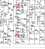
A further set of measurements is from ground to the two points circled here. Again compare to the good channel. You should see similar but opposite polarity voltages on these two points.
You are going to need steady fingers for this but measurement rather than random swapping of parts is always key if possible.
Look at R328 and also R428 in the other channel. When the amp is on lets see what voltage you have across these resistors. It should be very low and similar between channels.
Lets set the bias preset to give minimum bias on both channels for consistency (so the bias transistor in circuit and not linked out. Preset to appear as 500 ohm, all as before).
This measurement will see if the front end is trying to compensate for some imbalance within the output stage. That's the first measurement.
The second one is to measure the voltage from ground to these two resistors. I would expect the voltage to be quite low, perhaps just 0.5 a volt or so either way of ground potential. This measurement also helps see if there is an imbalance.
A further set of measurements is from ground to the two points circled here. Again compare to the good channel. You should see similar but opposite polarity voltages on these two points.
Attachments
Look at R328 and also R428 in the other channel. When the amp is on lets see what voltage you have across these resistors. It should be very low and similar between channels.
Lets set the bias preset to give minimum bias on both channels for consistency (so the bias transistor in circuit and not linked out. Preset to appear as 500 ohm, all as before).
This measurement will see if the front end is trying to compensate for some imbalance within the output stage. That's the first measurement.
Sorry for the slow response - I got an emergency call from work to fix something.
So - with preset on max for both channels.
R328 (left channel)
Across => 0.6mV
To GND => 28.6mV
R428 (right channel)
Across => -1.4mV
To GND => 95.3mV
To GND
A further set of measurements is from ground to the two points circled here. Again compare to the good channel. You should see similar but opposite polarity voltages on these two points.
Checking these now...
- Home
- Amplifiers
- Solid State
- A sorry tale of woe and stupidity: NAD C370