This may sound a strange thing to do but when the amp is on and the offset is near zero do you still hear a pop if you select/deselect the speakers using the front panel switches?
No pops when switching in/out of the speaker sets 😉
OK, it had to be checked.
I'm assuming you haven't a scope so lets try a little trick instead. If you connect a resistor and a cap in series across the speaker output do you see the same offset voltage across the cap as across the terminals. Lets say use a 1k to 10k resistor and a small cap. A non polarised type would be best like a 0.1uF but even a small electrolytic would do.
The R and C form a filter that will remove any high frequency AC and leave just the average DC value.
Any big difference in the steady state offset result.
Don't do this yet... but maybe we should try full mains, and I think we just have to do that at some point to be sure we're not chasing a non existent issue... but of course there is always a risk doing this.
Have to go 🙂
Attachments
No pops when switching in/out of the speaker sets 😉
That could be a good sign then.
OK, it had to be checked.
I'm assuming you haven't a scope so lets try a little trick instead. If you connect a resistor and a cap in series across the speaker output do you see the same offset voltage across the cap as across the terminals. Lets say use a 1k to 10k resistor and a small cap. A non polarised type would be best like a 0.1uF but even a small electrolytic would do.
No scope i'm afraid.
I wired up a 10uF electrolytic in series with a 10k resistor.
The steady state offset is pretty much identical across the cap as across the terminals. 😉
Don't do this yet... but maybe we should try full mains, and I think we just have to do that at some point to be sure we're not chasing a non existent issue... but of course there is always a risk doing this.
Oops too late! I already gave this a go with the preset back to 500 ohms.
No smoke or bangs - the speaker still pops though.
Have to go 🙂
Take care and thanks again Mooly 🙂
Good to know it survived full mains 😉
Its quite difficult keeping track of this mentally without actually having a physical item in front of me so if any of these questions seem a bit random...
You mentioned in post #43 that R337 had failed open circuit.
We could do with looking at the possible paths the current needed to zap that resistor might have flowed and that is most like via R338 and R339 and L302.
Those very low value resistors would be worth a second look. Some of these types can go high in value by just a few ohms and if that was intermittent/variable it could cause issues.
When isolated they should read pretty much exactly as marked plus the series resistance of your meter leads which is probably around 0.2 ohm.
Just thinking aloud now... so we are pretty sure the output isn't oscillating so that means the noise at power off seems to be caused by the offset changing rapidly in the few 10's of milliseconds between mains disappearing and the relay dropping out.
So is the offset changing with a change in supply voltage and if so why.
We should always measure the rails in any fault-finding exercise. In particular are the - and + 68 volt lines correct. These feed the front end section of the power amp.
We need to measure these and confirm they are OK.
Are the - and + 18 volt supplies OK? These are across the Zener diodes D301 and D302.
The 10k feed resistors R310 and R316 would be prime suspects as they are listed as 0.25 watt parts and they dissipate... 0.25 watts 😱
We could do with looking at the possible paths the current needed to zap that resistor might have flowed and that is most like via R338 and R339 and L302.
Those very low value resistors would be worth a second look. Some of these types can go high in value by just a few ohms and if that was intermittent/variable it could cause issues.
When isolated they should read pretty much exactly as marked plus the series resistance of your meter leads which is probably around 0.2 ohm.
Will double check these again 😉
We should always measure the rails in any fault-finding exercise. In particular are the - and + 68 volt lines correct. These feed the front end section of the power amp.
We need to measure these and confirm they are OK.
Will do - what is the best ground source to use when checking the rails? TP4? One of the connector pins like pin 4 of CZ304?
Are the - and + 18 volt supplies OK? These are across the Zener diodes D301 and D302.
The 10k feed resistors R310 and R316 would be prime suspects as they are listed as 0.25 watt parts and they dissipate... 0.25 watts 😱
Will check these too 😉
R338 => 3.6 ohms (marked as 3.3)
R339 => 5 ohms (marked as 4.7)
So they look OK, both are +0.3 ohms which will be the leads of the meter.
R339 => 5 ohms (marked as 4.7)
So they look OK, both are +0.3 ohms which will be the leads of the meter.
Those rails are OK but how about these? Are we on full mains now or back to the bulb?
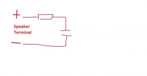
TP4 is perfect but using test points makes me nervous as it's so easy to slip with a probe. The speaker negative terminals should be as good. You can always do a quick confirmation that no voltage difference is present between them.
TP4 is perfect but using test points makes me nervous as it's so easy to slip with a probe. The speaker negative terminals should be as good. You can always do a quick confirmation that no voltage difference is present between them.
Attachments

TP4 is perfect but using test points makes me nervous as it's so easy to slip with a probe. .
🙁 Just as you posted that I indeed managed to slip with a probe.
I tested D302 and got 17.4V.
I went to test D301 and slipped - a small flash, not really any bang just a small fzzt.
Anyway, I frazzled D301 and will need a new one. I tested all the resistors around it and they are OK...bah!
After testing with mains I have been back on the bulb since.
Obviously I can't continue testing until I have replaced the zener diode but where would be the best place to test the +/-V68 you marked?
speaker terminal for ground but where is safest/easiest to get at the 68V?
speaker terminal for ground but where is safest/easiest to get at the 68V?
i find hook clips good for testing
hook one end on scope probe and other end on the pcb.
then turn amp on with no "slippage" problems.
hook one end on scope probe and other end on the pcb.
then turn amp on with no "slippage" problems.
i find hook clips good for testing
hook one end on scope probe and other end on the pcb.
then turn amp on with no "slippage" problems.
Yeah, good idea - I only have the long needle like probes here - I will order some of the retractable hook types. 😉
Far too easy to slip a mm or 2 and cause mayhem
The manual just says: 18V 0.5W for the zener.
Do these look for replacements?
www.digikey.com/product-detail/en/1N5248BTR/1N5248BFSCT-ND/1532772/?itemSeq=333522649
1N5248BTR at DigiKey.
Sadly they don't stock the fluke test hooks but these look like they should fit:
www.digikey.com/product-detail/en/5911B/501-2228-ND/6125659/?itemSeq=333528660
501-2228-ND Pomona grabbers at Digikey
Last edited:
Hmm... accidental shorts, it is so easily done. Do you know what you touched and to where...
If it was a rail to the Zener then the Zener is probably short. If it was 'something else' to the Zener then you have pulled current through other parts which may have caused a problem.
That replacement looks fine, it dissipates less than 100 milliwatts in circuit.
If it was a rail to the Zener then the Zener is probably short. If it was 'something else' to the Zener then you have pulled current through other parts which may have caused a problem.
That replacement looks fine, it dissipates less than 100 milliwatts in circuit.
Hmm... accidental shorts, it is so easily done. Do you know what you touched and to where...
If it was a rail to the Zener then the Zener is probably short. If it was 'something else' to the Zener then you have pulled current through other parts which may have caused a problem.
That replacement looks fine, it dissipates less than 100 milliwatts in circuit.
Pretty sure it was the little bar that runs directly underneath the zener - 3J24.
This appears to connect R309 with R310 along the +V68 track - fingers crossed it was only the zener that got hurt.
The parts should arrive on Thursday- along with the hook type probes. Hopefully they will help me avoid more probing slips.
OK 🙂
So it looks like the +68v line got shorted to the Zener. If it was the striped end of the Zener then the Zener will be zapped. If it was the other end then that is ground and the Zener would be OK.
Either way the +68v line took a hit. Now that line is stabilised and so it's worth checking the 33 ohm fusible resistor and also that the transistor isn't short circuit. The resistor should protect the transistor but you never know.
Attachments

OK 🙂
So it looks like the +68v line got shorted to the Zener. If it was the striped end of the Zener then the Zener will be zapped. If it was the other end then that is ground and the Zener would be OK.
Either way the +68v line took a hit. Now that line is stabilised and so it's worth checking the 33 ohm fusible resistor and also that the transistor isn't short circuit. The resistor should protect the transistor but you never know.
Yes, that resistor looks like its gone open - the transistor looks OK.
Going to be a pain to swap out that resistor - i'll have to remove the main board which doesn't look easy.
I'm having trouble finding this resistor.
There don't seem to be any 33 ohm 1/4W wirewound resistors in any of the stores I know about - DigiKey, Mouser, Elfa...
There don't seem to be any 33 ohm 1/4W wirewound resistors in any of the stores I know about - DigiKey, Mouser, Elfa...
DigiKey have some that a carbon film but I suppose this will not do?
www.digikey.com/product-detail/en/yageo/CFR-25JB-52-33R/33QBK-ND/1687
www.digikey.com/product-detail/en/yageo/CFR-25JB-52-33R/33QBK-ND/1687
- Home
- Amplifiers
- Solid State
- A sorry tale of woe and stupidity: NAD C370