Starting mods today, thanks Dimitri for help.
Are there other values for the input impedance, the 2 23k resistors?
JP
Are there other values for the input impedance, the 2 23k resistors?
JP
I stumbled upon this today (explanation of the Schoeps mike pre-pre, if I can call it that).Since virtually every Schoeps microphone (and many others use an open-loop JFET phase splitter running at 1mA or so I think we're in good company.
https://www.youtube.com/watch?v=e5xenXTwAzo&t=8m4s
-Alex
I stumbled upon this today (explanation of the Schoeps mike pre-pre, if I can call it that).
https://www.youtube.com/watch?v=e5xenXTwAzo&t=8m4s
-Alex
Yes, he makes the common mistake of saying they use a big FET with high Cin which is wrong. Some well meaning modders do this all the time but the noise is dominated by the G Ohm bias resistor and the capsule capacitance.
Thanks Scott. Indeed I have seen schematics with the 2sk170 in that position. There is no noise advantage, and you lose a few dB output because the high capacitance loads the capsule? What would you use instead?
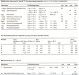
Here´s the first schoeps schematic that came up on a google search. It indicates BC264. And here´s the relevant data from a datasheet in german. Much lower capacitance than the K170. Comparable Rauschfaktor at 0,5dB, but the Equivalent Rauschspannung is listed as 40 nV/sqrt(Hz) versus 1dB typical for the K170@1mA.
-Alex
Attachments

Last edited:
Much lower capacitance than the K170. Comparable Rauschfaktor at 0,5dB, but the Equivalent Rauschspannung is listed as 40 nV/sqrt(Hz) versus 1dB typical for the K170@1mA.
-Alex
These numbers don't really reflect the application. Noise figure re: 1M and spot noise at 10Hz are not indicators of the noise in the microphone application. If the FET's have a reasonably low noise corner the noise of an equivalent resistance of about .7/gm would be the number to use. Selected J305's do remarkably well, my favorite 2SK222 is unfortunately obsolete with rare stashes of NOS parts here and there.
I was told Rode uses SMT versions of the J305 in their mic that achieves 5-7 dBA noise which is not audible in any normal recording environment.
EDIT - Forgot to mention the back plate hole patterns used to tune many capsules have a real acoustical resistance component which often dominates the noise in the important presence region anyway.
Last edited:
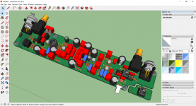
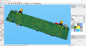
A bit of progress.
Patrick
.
Very nice! I see you put in the gate stoppers, fingers crossed that it's all you need.
Are you worried about oscillation ?
I don't really see a reason why it should ??
Being SMD, I can always change their value from 0 ohm to anything else.
Or even replace by ferrite beads.
We shall see,
Patrick
I don't really see a reason why it should ??
Being SMD, I can always change their value from 0 ohm to anything else.
Or even replace by ferrite beads.
We shall see,
Patrick
Are you worried about oscillation ?
I don't really see a reason why it should ??
One learns to always worry about oscillation. 😉
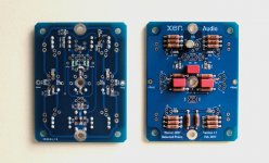
I've noticed a few pcbs on the thread... are some being produced or can someone who has made some for personal use spare one for me?
Where? I don't think anyone knows you are done or anything or the sort, or where the published document is at??
Design finished, see published documentation.
No demand for my PCB so no PCB produced.
JP
Well, I will officially pledge myself as the first interested party.
Lord knows I've pledged myself to be the first guinea pig in much worse.
Where? I don't think anyone knows you are done or anything or the sort, or where the published document is at??
A page or so back he has a nice color sketch up of the pcb populated with parts.
- Home
- Source & Line
- Analogue Source
- A simplified universal differential or single ended phono preamp