Scott,
Thanks for the Spice models, I was happy to see they are identical to mine.
I changed to +/- 15 volt supply and adjusted R1 to 47 Ohm to have 5mA current flowing through all Fets.
Gain was 14.75 or 23.4dB in this setting.
Going from 3mA to 5mA per Fet lowered the noise by 1dB from 117nV to 105nV, or to an equivalent input noise of 0.74nV/rtHz.
Does it make sense to increase current even further ?
With a 10mVrms@10Khz input signal I found the same -90dB THD as you mentioned.
Hans
When going to 4 double Fets at the input, still keeping 10mA going through R1, meant increasing R1 to 67 Ohm, giving a gain of 21.9 or 26.8dB.
Noise was now 81.5nV from 20Hz to 20Khz, or an equivalent input noise of 0.58nV/rtHz.
To get 0.4nV/rtHz, I expect that 4 quadruple Fets will have to be used.
Hans
Noise was now 81.5nV from 20Hz to 20Khz, or an equivalent input noise of 0.58nV/rtHz.
To get 0.4nV/rtHz, I expect that 4 quadruple Fets will have to be used.
Hans
When going to 4 double Fets at the input, still keeping 10mA going through R1, meant increasing R1 to 67 Ohm, giving a gain of 21.9 or 26.8dB.
Noise was now 81.5nV from 20Hz to 20Khz, or an equivalent input noise of 0.58nV/rtHz.
To get 0.4nV/rtHz, I expect that 4 quadruple Fets will have to be used.
Hans
I think juggling the currents and using one parallel pair could get close (BTW you don't have to parallel in powers of two with this topology if you think about it). I picked the 0.4nV number because John's customers were happy at that level and I remain interested in a solution that allows the customer to adjust the cartridge loading. My observation is that folks who play with these very expensive toys like to have that option. I'll play some more tonight.
As a last step I inserted 4 quadruple input Fets, still keeping the current through R1 at 10mA.
Noise from 20Hz to 20Khz was now 66.8nV, calculating in 0,47nV/rtHz.
Increasing the current through R1 to 20mA and changing R5 to R8 from 422 to 180 Ohm to double the current through the folded cascode, resulted in 59.7nV or 0.42nV/rtHz.
In both cases Overall Gain was kept at 20dB by adjusting R11 / R13.
Hans
Hi Guys,
Sorry Scott for going off-topic. But, the talk about paralleling more Fets, made me think if any of you have seen what Glen has been working on?
Low noise amplifier. - Page 5
Btw. Nice designs Scott. Given that 2SK170/BF862 is easier to get I tend to favor designs that use n-channels.
Mogens
Sorry Scott for going off-topic. But, the talk about paralleling more Fets, made me think if any of you have seen what Glen has been working on?
Low noise amplifier. - Page 5
Btw. Nice designs Scott. Given that 2SK170/BF862 is easier to get I tend to favor designs that use n-channels.
Mogens
Hi Guys,
Sorry Scott for going off-topic. But, the talk about paralleling more Fets, made me think if any of you have seen what Glen has been working on?
Low noise amplifier. - Page 5
Btw. Nice designs Scott. Given that 2SK170/BF862 is easier to get I tend to favor designs that use n-channels.
Mogens
I miss Glen, Ovidu did one of these too with the massively parallel BF862's. We used to discuss these back in the day all the time, a lot of nice ideas flew back and forth.
If you want to be practical and not so much a purist the very first circuit could probably be made with all BF862's subbing PNP's for the two PFET's and it would work very well.
I don't want to be rude, but when I see those diagrams with loads of paralleled Fets that have to well be matched trying to approach the simulated results, not to speak of very high susceptibility to oscillations, I'm starting to like John Curls super simple design more and more as a head amp.
And since it is battery fed it is completely floating and can because of that be regarded as differential-in / differential-out IMO.
And if you don't need the 0.27nV/rtHz which will be the case for most applications, you can half the amount of transistors, now running at twice the current per transistor and still have a whopping 0.33nV/rtHz.
Even one set of ZTX851/ZTX951 running at 4.4 mA gives you a fantastic 0.40nV/rtHz equivalent input noise.
THD is low at -90dB for 10mVrms@1Khz
Hans
John Curl's patent had four 2N4401s in parallel (Rbb_effective = 40 / 4 = 10 ohms) and four 2N4403s in parallel (Rbb_effective = 40 / 4 = 10 ohms), using the lowest Rbb transistors he knew about in 1977.
Whereas today, a single Zetex device has much lower Rbb (< 2 ohms) and they are so cheap that you can easily afford to buy ten & pick out the two that match best. Then John's emitter ballasting resistors further improve the effective matching.
And oh by the way, you could buy some super low leakage diodes like 1N3595, combine them with super low capacitance diodes like BAV21, and build a wall wart powered trickle recharger with reed relays and super precise current sources, to keep your NiMH 1.5V batteries charged up all the time.
_
Last edited:
And since it is battery fed it is completely floating and can because of that be regarded as differential-in / differential-out IMO.
Well no that's not true, apply a common mode signal and see, as Mark said it all collapses into a self biasing CE amplifier. Secondly the open loop gain is low with a 2 ohm source the gain is actually 30dB and not 40, it's OK this is audio in the end you just adjust the gain pot. But most importantly even John does not like virtual ground input setup circuits, he has stated here several times they sound like they are "underwater".
There is a large community of users that want to set the input termination on their MC pre-amps. When they can do this they find sonic benefit, so that is a design goal here a pre-amp that has a high enough input impedance that external passives can set the input termination.
At some point it's the same discussion of trade offs to get 1ppm distortion at 400W and 20K.
Question: How do you apply a common mode signal to something that is completely floating ? I think it cannot do anything else but to float up and down with the common mode signal. Output voltage won't change between the two pins, because input signal is not changing, so in fact CMRR is very high, given there is nowhere a connection to Gnd and output is fed into a differential input.Well no that's not true, apply a common mode signal and see, as Mark said it all collapses into a self biasing CE amplifier
Yes you have to adjust gain for every individual Cart. That's the case for all current input amps.Secondly the open loop gain is low with a 2 ohm source the gain is actually 30dB and not 40, it's OK this is audio in the end you just adjust the gain pot.
There are currently a number of (expensive) MC preamps on the market with a virtual gnd, or current input as they call it. Tests in Stereophile are quite positive, although that is no prove.But most importantly even John does not like virtual ground input setup circuits, he has stated here several times they sound like they are "underwater".
There is a large community of users that want to set the input termination on their MC pre-amps. When they can do this they find sonic benefit, so that is a design goal here a pre-amp that has a high enough input impedance that external passives can set the input termination.
At some point it's the same discussion of trade offs to get 1ppm distortion at 400W and 20K.
Also look at the Aurak preamp, not bad at all.
So like in many cases there are probably camps for voltage input and camps for current input and you are right with the 1ppm etc.
Hans
Last edited:
I think you two are in violent agreement as only tech types can be 🙂.
I'd still love to know what caused the 'underwater' effect John talks about.
I'd still love to know what caused the 'underwater' effect John talks about.
I think you two are in violent agreement as only tech types can be 🙂.
I know, sigh. John has stated this a few times here he (and I assume his posse) do not like the sound of virtual ground MC stages. So I will pursue the alternative avenue, if you want a bi-polar transistor with minimum possible rbb a couple of guys from Philips derived the geometry (I lost the paper) but it is not rocket science. In fact I probably have the only samples left in existence. If NASA wanted a super-beta transistor with .1 ohm rbb that took up a full cm on a side of wafer we could just make it, and it would just cost $$.
Hans, I assume the ground connection is propagated throughout the system all the way to the safety ground wire.
Last edited:
Here are some examples
B.M.C. Phono MCCI phono preamplifier | Stereophile.com
I'll pass, the technical content here is on shall we say a basic level. If you think the .27nV and common base input is the bee's knee's just ignore me I'm used to it. BTW please note the thread through this review to never actually connect either end of the cart to ground lest the performance be void.
The main caution is that you must maintain "ground free" connections from your turntable. The shield must not be connected to any of the four cartridge wires. That means that Rega Research turntables (and Rega's separate tonearms) will need the ground connection broken between the arm and the cartridge's blue "earth" pin.
Last edited:
Bill,I'd still love to know what caused the 'underwater' effect John talks about.
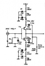
I might have an idea what caused the "underwater effect" at least for John Curl's Patent circuit.
Current flowing through the Cart is heavily dependant on equal voltages of both batteries.
The slightest mismatch already results in a relative large DC current, hundreds of microamps, flowing through the Cart.
It would amaze me if this had no effect on the sound, even so more because Batteries are not even stable in their voltages when in use.
So I will come with a "modernised" version of this patent, now taking care of this problem.
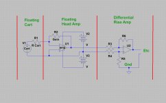
And of course what Scott also mentions, is that Carts (and this Amp) should be fully floating when using a virtual Gnd input.
An ideal scenario for a connection to a differential input, see below.
Hans
Attachments
It is probably a LOT easier to build a ripple-and-noise-free, low output impedance, extremely precise pair of voltage regulator circuits (plus and minus 1.500 volts), than to build a world class MC stepup amplifier. Especially when the design is DIY and not constrained to meet a cost target or a max-footprint size requirement.
what can be simpler? from 1982
http://www.4tubes.com/SCHEMATICS/BY-BRAND/Italien/pre_Quad34.jpg
http://www.4tubes.com/SCHEMATICS/BY-BRAND/Italien/pre_Quad34.jpg
Attachments
Last edited:
what can be simpler? from 1982
http://www.4tubes.com/SCHEMATICS/BY-BRAND/Italien/pre_Quad34.jpg
How close are the N and P beta running, at large currents there will be some DC current in the cartridge (probably not a problem). OTOH supply sequencing could be.
I see the ZTE devices were known a while back even while the RHOM devices were in vogue. Do they really need no selection for popcorn or other 1/f noise?
Last edited:
And of course what Scott also mentions, is that Carts (and this Amp) should be fully floating when using a virtual Gnd input.
An ideal scenario for a connection to a differential input, see below.
Hans
Where's pin 1? You need to complete the system with shielding, etc. in a way that won't pick up RF or violate code.
I assembled about twenty of them, with and without overall FB as shown here, but with servo instead emitter capacitors. 1/f corner has lower frequency than LSK389Do they really need no selection for popcorn or other 1/f noise?
- Home
- Source & Line
- Analogue Source
- A simplified universal differential or single ended phono preamp