Got it, thank you.Referred to input i.e. Friis' formula. As you can sum noise going forward as a referred to output number, you can go backward for a referred to input number.
4nV/rt-Hz added at the output of a 26dB amplifier looks like .2nV/rt-Hz at the input. All noise is rss added for a total (.2**2 + .27**2 = .34**2). For phono I would add the surface noise but some don't.
That's why I took 26dB gain.
The 0.24nV/rtHz translates to 4.8nV/rtHz at 26dB gain.
With 20dB it would be only 2.4nV/rtHz, quite a bit below the 4nV/rtHz noise from the MM amp.
Hans
Got it, thank you.
That's why I took 26dB gain.
The 0.24nV/rtHz translates to 4.8nV/rtHz at 26dB gain.
With 20dB it would be only 2.4nV/rtHz, quite a bit below the 4nV/rtHz noise from the MM amp.
Hans
Good, I just want to repeat an earlier point the SNR at the vinyl surface is what matters (67dB or so). No amount of circuit sophistry can change that, unlike RF we can't change the antenna gain. Phono stages with 80dB SNR are just numbers.
I couldn’t agree more and have mentioned very often that a S/N of 76 dbA with Cart connected is good enough.
But when you get it almost for free there is nothing against it.
And this was the first time a came across such a case, low cost and simple.
Hans
But when you get it almost for free there is nothing against it.
And this was the first time a came across such a case, low cost and simple.
Hans
. Phono stages with 80dB SNR are just numbers.
Yes.And phono stages that meet that with the cart connected are just silly. But for every sensible solution someone will be excessive. Oh..wait...😉
While I was still working on the "old" version, I missed all these. 🙂
But perhaps back to the phono.
I had a complementary version for phono on in Spice with 1000x gain at 1kHz without a MC pre.
But it requires too many 2SJ74s.
Not a problem for me, but for most others.
Which was why I decided to stay with the original topology.
Also allows me to use 2SK372 for all the N devices.
We'll find out in a couple of weeks whether I have too much gain and hence a DC drift issue.
As Scott just said you can use BF862 and 2SA1312 as well.
Already checked them in Spice last year.
But then you need to watch voltages for the BF862, or better cascode them with MMBFJ111.
Put them on a 5x7mm PCB and you have a TO92 equivalent.
😉
Cheers,
Patrick
Being sensible for a second has anyone looked at the Onsemi CPH5905? slightly noisier than BF862 but has build in cascode NPN and just a few pennies.?
Hi Bill,
Thanks, that's actually rather nice. Perhaps we could persuade Scott to measure one, like he did with BF862, if we got him some 😉
Mogens
Thanks, that's actually rather nice. Perhaps we could persuade Scott to measure one, like he did with BF862, if we got him some 😉
Mogens
> Being sensible for a second has anyone looked at the Onsemi CPH5905?
Yes, but a J111 cascode is self biasing and does not require extra components.
So you can replace a 3-legged 2SK170 directly without any change in circuit.
Patrick
Yes, but a J111 cascode is self biasing and does not require extra components.
So you can replace a 3-legged 2SK170 directly without any change in circuit.
Patrick
Being sensible for a second has anyone looked at the Onsemi CPH5905? slightly noisier than BF862 but has build in cascode NPN and just a few pennies.?
Waly has recommended its use on a few occasions, especially atter bf862 went eol. Think Dimitry has it in his jfet article: marginally worse noise, marginally lower corner though.
Does require the extra bias bits but nice for extremely compact layouts.
> Does require the extra bias bits but nice for extremely compact layouts.
By the time you add all the bits require to bias the base, it is not so compact anymore.
I personally shall still choose J111+BF862 any time.
Cheers,
Patrick
By the time you add all the bits require to bias the base, it is not so compact anymore.
I personally shall still choose J111+BF862 any time.
Cheers,
Patrick
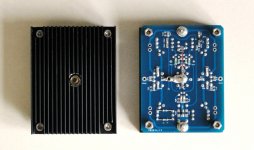
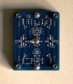
Wurcer Balanced RIAA for MC -- Protos
The good news is that it works first time.
All DC values as expected.
One channel does not even need any differential trimming.
The other one has a 25µA offset which was trimmed at the bottom current source at the 2nd stage.
So now both channels have common mode DC ~ 20mV (with servo).
Differential DC is within +/-200mV over time with no servo.
Bear in mind I have very large gain at DC, this is not too bad.
Of course it only eats up a bit of voltage, and has no consequence at the output.
This is because I have a 16Hz rumble filter just before the output dource followers.
So any small DC has no consequence.
Need to do some work first to get a low enough balanced signal source for frequency response measurements.
Patrick
.
Attachments
> Does require the extra bias bits but nice for extremely compact layouts.
By the time you add all the bits require to bias the base, it is not so compact anymore.
I personally shall still choose J111+BF862 any time.
Cheers,
Patrick
Can't argue with that as long as you have a stash of bf862's to work with!
You can also get 2SK3557-6 which is the Sanyo (On Semi) equivalent to BF862.
We have both.
🙂
Patrick
We have both.
🙂
Patrick
The price is noise.
Measurements Rate SMT Low-Voltage n-JFETs Under Consistent Conditions | Electronic Design
Patrick
Measurements Rate SMT Low-Voltage n-JFETs Under Consistent Conditions | Electronic Design
Patrick
Thanks for grabbing the link for Dimitri's article and glad to hear your prototype is well behaved. Excellent craftsmanship as usual.
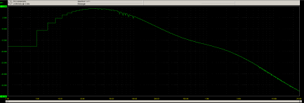
Completed all measurements today for both channels.
Essentially identical. Gain at 1kHz 1100 & 1090 respectively (~0.1dB).
So pretty much as intended.
DC offset at the outut followers < 2mV over an hour.
Frequency response also agrees to simulation to < +/-0.2dB from 30Hz to 2.5kHz.
(limited by resolution of the frequency plot)
Quite pleasured with the results actually. 🙂
All thanks go to Scott, without saying.
Next is to design a regulator board to stack directly under the phono PCB.
Patrick
.
Attachments
Quite pleasured with the results actually. 🙂
All thanks go to Scott, without saying.
.
Thanks to you, and Dimitri. My attempt to use a lot of unavailable JFET's to extend this to MC probably does not appeal to many people.
So folks don't miss it Dimitri's measurements show that the LSK part was free of GR noise which is evident in several of his other samples. Someone should check the P parts, it would be nice to have at least some P channel FET's that you could trust.
This is one of the reasons why I stayed with the original circuit and only increased the gain to 60dB at 1kHz.
This was meant to cater for MC without the need for an additional headamp.
Apart from a quad of 2SK372GR for the input stage, one can do this with only 2SK170s or even 2SK117.
2SK117 is of course still available from Mouser in SMD as 2SK209GR.
(2x 2SK209 is close enough to 1x 2SK170, or 1/2x of 2SK372)
Although I used a pair of 2SJ74s for the cascode, one can equally use 2SA1312BL to replace.
At least in simulation there is little penalty.
So this can still be built without having to source 2SJ74s.
If one would reduce gain for MM only, then even 2SK372 is not necessary, and 2SK170 will do.
Patrick
- Home
- Source & Line
- Analogue Source
- A simplified universal differential or single ended phono preamp