Was there some switch or relay not shown to go between MM and MC? The gain looks a little high but the component values are a little hard to read sometimes.
EDIT - I see they are daughter cards.
EDIT - I see they are daughter cards.
Last edited:
Where's pin 1? You need to complete the system with shielding, etc. in a way that won't pick up RF or violate code.
I thought that would speak for itself, however here it is in the image below.
Neither the Cart nor the headamp should have any connection to chassis or shielding.
Attachments

I thought that would speak for itself, however here it is in the image below.
Neither the Cart nor the headamp should have any connection to chassis or shielding.
By balanced I mean for 2V out pins 2 and 3 are each 1V and out of phase without a common mode reference what achieves the division? Battery operated mics work fine but without a transformer or two explicit outputs they end up psuedo-balanced. In your first picture the head amp is connected to ground through the resistive differential receiver. I assume your second picture shows the entire chassis/shield system grounded only at the pre-amp.
Last edited:
Sorry Scott, we are thinking along different lines.By balanced I mean for 2V out pins 2 and 3 are each 1V and out of phase without a common mode reference what achieves the division? Battery operated mics work fine but without a transformer or two explicit outputs they end up psuedo-balanced. In your first picture the head amp is connected to ground through the resistive differential receiver. I assume your second picture shows the entire chassis/shield system grounded only at the pre-amp.
A balanced output does not need to have two out of phase outputs plus a common mode reference. Look for instance at the Bruno Putzeys Balanced Preamp.
When feeding into a differential input all you need is a voltage difference but absolutely no common mode reference.
If this is what you call pseudo balanced, that's O.k. for me.
I will make a new and more complete picture to make things clear.
Hans
By balanced I mean for 2V out pins 2 and 3 are each 1V and out of phase without a common mode reference what achieves the division?
Sorry Hans I was't thinking, age is getting to me lately. Standard practice is to connect a ground to the mic somewhere inside, obviously if you don't the current has nowhere else to go.
I'm still not sure this is best for RFI/EMI rejection but I have not tried it.
Does raise the question of best practice when you aren't powered off the mains. Current plan if ever completed is to have phono stage and ADC in the same box, powered off silentswitcher. If I use optical to the miniDSP there is no safety need to connect the analog side to PE. If I use AES then the screen would provide that via the poweramps.
Then there is the old adage of grounding at the point of lowest signal, which from a safety perspective is very silly.
Then there is the old adage of grounding at the point of lowest signal, which from a safety perspective is very silly.
Bill,
Would it be possible for you to make some sketch with all the components you are talking about and their connections ?
Hans
Would it be possible for you to make some sketch with all the components you are talking about and their connections ?
Hans
Sure, if it is not pulling the thread too far off it's currently fairly focussed discussion, otherwise will start a new one for this topic.
Sure, if it is not pulling the thread too far off it's currently fairly focussed discussion, otherwise will start a new one for this topic.
I tend to follow standard practice like Bill Whitlock's AES presentation. I guess I've spent too many years where things have to work no matter what they get plugged into. Like fig 1 and 2 in Jim Brown's presentation I have never seen in practice the common of a mic/preamp not connected to the shield/case/body (but correctly as shown). As was pointed out if this can't be done warnings must ensue.
http://www.audiosystemsgroup.com/Pin_1_Revisited_Part_2.pdf
Below the simulation results of the Curl Amp feeding a differential Riaa preamp.
Gain of the preamp is set at 20 and for the Riaa amp an arbitrary gain value of 50 at 1Khz,
V3 and V4 are two batteries feeding the Curl amp.
Inside a servo takes care of the voltage supplies, preventing the Cart current ever to exceed 1uA.
At the same time another circuit connects and disconnects the Cart when the voltage supply is not yet or no more settled, preventing current spikes flowing into the Cart.
Rout of Head+ is 100Ohm, so in order to make the output balanced, a second 100Ohm resistor is added in the Head- line.
Transfer is measured with the floating source B1. CMMR is measured by connecting V2 between R3 and R4.
CMMR, being the difference between the gray and the red line, starts at 80dB up to 1Khz and goes from there to 60dB at 20Khz.
The details of the improved Curl Amp to follow in detail.
Hans
Attachments

I tend to follow standard practice like Bill Whitlock's AES presentation. I guess I've spent too many years where things have to work no matter what they get plugged into. Like fig 1 and 2 in Jim Brown's presentation I have never seen in practice the common of a mic/preamp not connected to the shield/case/body (but correctly as shown). As was pointed out if this can't be done warnings must ensue.
Just to ensure we are not at x-purposes I am envisioning the case similar to when you are using your field recorder to digitise a test signal. Screens are still connected, but there is no 'ground' connection as nothing in the signal path is mains powered. The question really was, is there any benefit in adding that connection for a static installation.
Just to ensure we are not at x-purposes I am envisioning the case similar to when you are using your field recorder to digitise a test signal. Screens are still connected, but there is no 'ground' connection as nothing in the signal path is mains powered. The question really was, is there any benefit in adding that connection for a static installation.
I'd have to think about it. You are right my pre-amp is running off of a silent switcher off of a 5V battery pack. Everything could float, OTOH I could put the TT and class D amp on a 12V battery and nothing at all is mains connected.
There are several issues IMO to be regarded when connecting equipment.
The chassis of every piece of equipment connected to mains for it's power supply, MUST be connected to mains Gnd, period.
A Battery operated apparatus has no such need, think of a battery operated walkman, iPhone, transistor radio, etc.
EMI/RFI shielding is a separate topic and is just as important for battery operated equipment as it is for a mains operated version.
But there is an extra bonus for floating (battery operated) equipment when feeding into a differential input.
Because with the correct precautions it can be made balanced (if it not already is like a Cart), having great advantage over SE in induced noise suppression, an advantage that SE fails to offer, since there is no CMRR available.
This is true for a TT, but also for a battery operated head amp in between feeding into a differential preamp.
When no differential input at the end of the chain is available, there is not that much advantage from a noise suppression point of view in making things floating .
But even in case of connecting two mains operated pieces of equipment, both individually connected to mains gnd, might it be better not to connect pin1 at both ends, because there might be a different potential on both chassis for several reasons resulting in unwanted equalisation currents through the cable shield. See pin 1 OEO or one end only article in LA Vol 10 as supported by Bill Whitlock.
Hans
P.S. R11 in #270 should be 61k instead of 50K to give the correct 47K input resistance for a MM amp. However, this has no effect on CMMR.
Last edited:
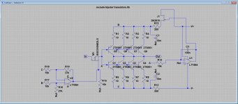
And here John Curl's Extended version of the Head Amp.
Since the ZTX transistors are almost for free at 0.6 Euro/each, I have not reduced the amount of the original design, although this can be done.
Further, I have chosen for a gain of 20 to get some noise margin over the noise from MM stage coming behind this head amp.
In this setup, equivalent input noise is an unbelievable 0,24nV/rtHz.
You will probably never need this, but it comes almost for free and it doesn't hurt either, with no HF issues as paralleled high frequency Fet's can cause.
Three 1.5 Volt batteries are used. One for the unregulated negative supply, and two for the regulated positive supply.
Positive supply for the circuit is made with a LT1884 and a Fet.
The LT1884 having an ultra low offset voltage, takes care that the Cart voltage is always close to zero.
As a result Cart current will always stay below 1uA, independent of battery voltage, solving the biggest problem with the original circuit design, that may have caused the "underwater" sound.
A second LT1884 connects the Cart to the head-amp, once the supplies have settled at about +/- 0.5 Volt at points B and C in the diagram.
Connection is realised with a Mosfet, having a channel resistance of only several milliohms when switched on.
Since the Mosfet operates at a virtual gnd node, it's capacitances are playing no role.
In the THD simulations, no effects whatsoever of this additional Mosfet could be seen at all.
When power supply is switched on or off, this Mosfet immediately disconnects the Cart, preventing any current spikes through the Cart.
As can be seen in #270, Batteries are connected to V+, Null and V-.
Feedback resistor, depending on the Cart resistance is placed between In and Out.
For a gain of 20, this resistor has to be 137.5, 190 and 290 Ohm for a Rcart of resp. 2.5, 5 and 10 Ohm.
Total current drawn is slightly more than 6mA.
When using three 1500mAh penlites, it can be used for 250 hours.
Hans
Attachments
Further, I have chosen for a gain of 20 to get some noise margin over the noise from MM stage coming behind this head amp.
Hans I admire your enthusiasm. The resistive differential line receiver might not be a good choice then. The popular THAT InGenius line is ~25nV so 1.25nV RTI at 26dB gain. There are a lot of MM circuits out there at 4nV so that's a better total .34nV RTI. Typical MM stage with 20dB step-up transformer is .4nV or so (yes you can do better).
This started out as an all FET open-loop fun project for those who are interested, all these other solutions have been around for the proverbial 40yr. It would be rather fatuous to say that, by the numbers alone, the phono problem is yet to be solved.
Scott, I missed the beginning of this thread and was triggered by the heading "simplified" etc and by the Curl Patent shown recently.Hans I admire your enthusiasm. The resistive differential line receiver might not be a good choice then. The popular THAT InGenius line is ~25nV so 1.25nV RTI at 26dB gain. There are a lot of MM circuits out there at 4nV so that's a better total .34nV RTI. Typical MM stage with 20dB step-up transformer is .4nV or so (yes you can do better).
This started out as an all FET open-loop fun project for those who are interested, all these other solutions have been around for the proverbial 40yr. It would be rather fatuous to say that, by the numbers alone, the phono problem is yet to be solved.
It was not at all my intention to steer this thread into a different direction, so I will pull back with this Curl thing.
However, I can say that is was fun dealing with a Patent from long ago that still has potential in these days with fresh components.
Hans
Scott,
The differential line receiver that I used was just to show a complete picture, but allow me to ask, what exactly is RTI.
"There are a lot of MM circuits out there at 4nV so that's a better total .34nV RTI".
The 4nV is most likely 4nV/rtHz, but what is the other figure ?
Hans
The differential line receiver that I used was just to show a complete picture, but allow me to ask, what exactly is RTI.
"There are a lot of MM circuits out there at 4nV so that's a better total .34nV RTI".
The 4nV is most likely 4nV/rtHz, but what is the other figure ?
Hans
Hans: Would it be OK if I pulled out the useful bits into a new thread? I think this has enough merit to be discussed on its own, or at least in the context of application of the ZTX parts as a viable alternative to long gone 70s devices.
Bill,Hans: Would it be OK if I pulled out the useful bits into a new thread? I think this has enough merit to be discussed on its own, or at least in the context of application of the ZTX parts as a viable alternative to long gone 70s devices.
What a nice idea.
Scott,
The differential line receiver that I used was just to show a complete picture, but allow me to ask, what exactly is RTI.
"There are a lot of MM circuits out there at 4nV so that's a better total .34nV RTI".
The 4nV is most likely 4nV/rtHz, but what is the other figure ?
Hans
Referred to input i.e. Friis' formula. As you can sum noise going forward as a referred to output number, you can go backward for a referred to input number.
4nV/rt-Hz added at the output of a 26dB amplifier looks like .2nV/rt-Hz at the input. All noise is rss added for a total (.2**2 + .27**2 = .34**2). For phono I would add the surface noise but some don't.
Last edited:
- Home
- Source & Line
- Analogue Source
- A simplified universal differential or single ended phono preamp