This is a good primer. http://p10hifi.net/planet10/TLS/downloads/Dinsdale-Horns-3parts.pdf
We have come some ways since you would design a horn this way, but it lays down the principals.
dave
We have come some ways since you would design a horn this way, but it lays down the principals.
dave
Thank you Dave!
Is the rear shape of the Silbury and FHXL designed with that big radius because it is the opposite of the way the soundwave "comes out" from the mouth, so it helps to reflect back in a smoother way the soundwave into the horn?
What I've learned so far is that the horn must be as long as lambda/4 and that can be easily achieved.
Then the mouth perimeter must be bigger than lambda, if the speaker is against a wall, and bigger than lambda/2 if against the wall.
With a small compromise mouth can be lambda/4 in the former case and lambda/8 in the latter.
For 20Hz, lambda is 17 meters, so lambda/4 and lambda/8 are easily achievable.
Higher frequency is limited by the volume of the throat chamber, and must be designed to be not lower than three octaves below the cutoff.
The advantage of horns is also due to higher efficiency (50% vs 1-5% o closed enclosures and vented boxes), so smaller dispacement for the speaker, so less distortion due to the speaker and also less distortion due to adiabatic compression of the volume inside the horn.
Minimum distortion can be achieved loading both the rear of the speaker (for lows) and the front (for mids and highs), and they can overlap 10% giving 8 to 9 octaves from a single speaker. Are front horns harder to build, as I haven't seen many?
The curve, introduced by Ron Clarke in th eoriginal FH, makes the high aspect ratio mouth look more like the ideal circular mouth.
dave
dave
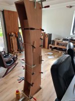
Silbury's beginning to take shape.. The internal baffles are 18mm BB while the external cabinets are a carbon fiber reinforced multilayer glue-up. Heavy is going to be an understatement when these all come together. Will be assembling the internals this weekend and then starting on the external carcass for unit #2.. I was toying with veneering the cabinet sides but such a monolith almost deserves to be a matte grey or white.


Really love this build allready...will start mine this w-e. but with more simple 18mm multiply configuration... what speakers will you be using? I plan to use a set of m10.2 to compare with my victors and FE168NS...
Thx.. I'll be using MAOP 11's.Really love this build allready...will start mine this w-e. but with more simple 18mm multiply configuration... what speakers will you be using? I plan to use a set of m10.2 to compare with my victors and FE168NS...

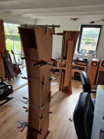
mine underway...started yesterday and still a lot to do...
BTW would you share the .STL file of your diffuser, I would like to 3d print it and I guess this is gonna take some time...I left the rear chamber unglued so I can still add it...
BTW would you share the .STL file of your diffuser, I would like to 3d print it and I guess this is gonna take some time...I left the rear chamber unglued so I can still add it...
Attachments
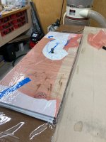
I wet laminated the carbon cloth between the sheet stock. I used System-3 laminating epoxy (slow hardener) primarily as it's slightly higher viscosity than the products from Total-Boat. I notch-troweled it on the wooden surface and then laid down the fabric into the wet epoxy, using a plastic smoothing tool to ensure full saturation of the cloth. Then a second thin layer of epoxy on the cloth and pre-treat the wood with the same epoxy as it (especially the MDF) sucks up so much resin that it would be easy to starve the carbon cloth; repeat for as many layers as you care to build. Finally the completed sandwich was wrapped in non-perf release film to protect my vac bag (https://www.roarockit.com/thin-air-press/) and allowed to cure for 24 hours. In my pre-construction testing a single layer does not impart much strength and 2+ layers were required to add meaningful stiffness. There was an improvement going from 2 layers of cloth (wood / carbon / wood / carbon / wood) to 3 layers (carbon / wood / carbon / wood / carbon / wood) (at the same total laminate caliper) but given the price of carbon cloth (~$70/m) the improvement wasn't meaningful.argoncat, what kind of glue did you use to bond carbon and wood?
BTW guys, beautiful job
Attachments
I used the great site (http://actools.tunetown.de/prd/) to design the diffuser to get it as close to size as possible. While the site will spit out an STL but I cannot edit them to trim the output size to the cavity and found 3D printing far to expensive to out-source. Thus, I took an afternoon and cut hundreds of small pieces of wood and assembled the diffuser piece by piece following the QRD map generated for the size / frequency / prime # from the site above.mine underway...started yesterday and still a lot to do...
BTW would you share the .STL file of your diffuser, I would like to 3d print it and I guess this is gonna take some time...I left the rear chamber unglued so I can still add it...
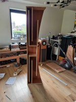
With a known width and arch rise I used a very flexible PVC pipe to trace the curve on 9mm MDF which was then cut on a bandsaw / manually sanded to match the drawn profile. With this as the master template its easy to flush trim rough cut side walls to template profile.Great built!
How did you trace and cut so perfectly the 1,8 meters long curve behind?
Page 11 of the Frugel-Horn Mk 3 outlines essentially the same technique.
https://frugal-horn.com/downloads/frugel-hornMk3-1v0-060518.pdf
dave
https://frugal-horn.com/downloads/frugel-hornMk3-1v0-060518.pdf
dave
I've bought two used MA10.3, previously installed in an OB project.
I'd like to slowly build two Silburies. Are plans available or it is needed to buy them?
They are planned to be installed in the living room, 13x4xh2.8 meters, around 3 meters far each other, pointing just in front of the middle of the sofa.
I'd like to slowly build two Silburies. Are plans available or it is needed to buy them?
They are planned to be installed in the living room, 13x4xh2.8 meters, around 3 meters far each other, pointing just in front of the middle of the sofa.
Thanks Dave and Scott, I have the plans now, and I will have the MA 10.3 by the end of the next week.
I like this solution ( https://www.diyaudio.com/community/...chamber-to-the-next-level.195469/post-2729763 ) that I've seen here too ( https://www.thomann.de/it/vicoustic_multifuser_wood_mkii_64_wood.htm ) but I've seen some discordant replies on it here.
How can it be implemented in the Silbury? What is the optimal frequency range? Will it still needed to dampen all five faces? What is the sonic benefit?
Thanks
Roberto
Another question comes from this other thread ( https://www.diyaudio.com/community/threads/acoustic-horn-design-the-easy-way-ath4.338806/ ): having a 3D printer, could I add a front horn to the Silbury and improve further the performance of the speaker?
Laid up at the moment with second virus in succession & I'm struggling to read off screens so apologies for the brevity. For the questions above in order
1/ A rear chamber diffuser was never included in the Silbury design by me; given the chamber dimensions & loading it is not something I see much value in (they may have advantages in other situations) as the wavelengths involved are already damped out with relatively small quantities of material that need to be there anyway
2/ Depends how you define 'improve'. Realistically, no -not of sufficient dimensions. A relatively large example might allow a reduction in damping in certain (certain) situations -Silbury is a high-gain design when optimally loaded & under those conditions needs some additional damping to balance the execess LF output over the nominal (always better to have too much than too little), albeit at the probable price of then needing HF EQ or a separate HF drive unit it's unlikely to be functional into the HF. A smaller minimally-loading front horn (waveguide) could be applied in more reasonable size but is unlikely to bring any real benefits to an Alpair 10.
- Home
- Loudspeakers
- Full Range
- A Silbury Build