Software now working perfectly with rotary encoder and IR. Circuit card design is good except some of the holes got smaller when I converted from Expresspcb to Gerber and some bigger components (screw terminal blocks) don't fit in holes so need to fix that in next iteration.
LDR control board is going to have the same problem with screw terminals but everything else should be OK so will assemble one of those in the next few days.
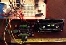
One change coming: designing a convenient Mute function running on the rotary encoder didn't work out -- will design a separate mute button input for the front panel. The IR remote mute feature currently works very well indeed.
Here is a picture of the encoder/IR/display controller card with display showing Volume converted to 0-100 range.
LDR control board is going to have the same problem with screw terminals but everything else should be OK so will assemble one of those in the next few days.
One change coming: designing a convenient Mute function running on the rotary encoder didn't work out -- will design a separate mute button input for the front panel. The IR remote mute feature currently works very well indeed.
Here is a picture of the encoder/IR/display controller card with display showing Volume converted to 0-100 range.
Attachments
Pardon me if I'm not following closely, but there are rotary encoders that have a push switch. This switch could be a mute function?
Software now working perfectly with rotary encoder and IR. Circuit card design is good except some of the holes got smaller when I converted from Expresspcb to Gerber and some bigger components (screw terminal blocks) don't fit in holes so need to fix that in next iteration.
LDR control board is going to have the same problem with screw terminals but everything else should be OK so will assemble one of those in the next few days.
One change coming: designing a convenient Mute function running on the rotary encoder didn't work out -- will design a separate mute button input for the front panel. The IR remote mute feature currently works very well indeed.
Here is a picture of the encoder/IR/display controller card with display showing Volume converted to 0-100 range.
Is this something you will eventually offer PCBs for, or offer as some type of kit?
I've never tried anything LDR before.
Thanks...
Pardon me if I'm not following closely, but there are rotary encoders that have a push switch. This switch could be a mute function?
Yes, I know that. I shouldn't post stuff like that here, things move too fast -- as soon as I do, it's OBE. Have now found a trick that really expands use of the encoder. I'm investigating and looks like I can do a whole lot more than just that. Stay tuned.
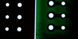
Back in post 461 I said that pcb holes got smaller when I converted from Expresspcb to Gerber. Well, the Expresspcb and Gerber files both show a .033 hole, but the boards are not the same, and the OSH Park board hole will not aqccomodate the part that the Expresspcb board will accomodate. I took a photo to demonstrate the difference in hole size. Pretty darned obvious when magnified. I'm looking for a different PCB fabricator. (These two boards are laid side-by-side with a back light to illuminate the holes so the difference you see is a true difference.)
Attachments
Is this something you will eventually offer PCBs for, or offer as some type of kit?
I've never tried anything LDR before.
Thanks...
Probably only as a fully functional board -- other options result in issues that I don't want to deal with.
One way the hole size problem may have arose is how your Gerber file is interpreted. Hole sizes can either be specified as a drill bit size (the unfinished hole) or as the diameter of the finished, plated hole. I believe your Gerber file was the result of what you wanted your finished size to be, but they interpreted it as a drill size.
Personally, I think it's better to specify the finished hole size, since there's no way that you could know their plating thickness, which is also not a constant among all PCB manufacturers. So, if you tell the board fabricator to interpret your Gerber file as finished hole diameters, they will convert each hole size to a new (larger) drill size so that after plating, you end up with the specified hole size, or slightly larger.
Personally, I think it's better to specify the finished hole size, since there's no way that you could know their plating thickness, which is also not a constant among all PCB manufacturers. So, if you tell the board fabricator to interpret your Gerber file as finished hole diameters, they will convert each hole size to a new (larger) drill size so that after plating, you end up with the specified hole size, or slightly larger.
Probably only as a fully functional board -- other options result in issues that I don't want to deal with.
Sounds good...when it comes to something like this, I'd rather buy something that I know has been tested and works as it should.
Any idea about pricing?
Any idea about pricing?
I'm still struggling with that, the latest setback with the pcb doesn't help. See post below for explanation of the undersized appearing holes on the OSH Park board.
Last edited:
Here's the explanation for the PCB problem I had, solved by David at Robot Room -- in short, I'd become accustomed to Expresspcb's out-of-tolerance-on-the-large-side holes. Here's my reply to his explanation and his explanation below.
David, that’s really good investigative work, I’m impressed, and thanks. This does seem to explain what happened -- I have used this size hole with this part for a long time simply because it always worked (from Expresspcb); but when I actually looked at the specification sheet for this Buchanan part I see that it recommends a 1.1mm hole -- .043 inches, and that would have taken care of everything. I have a few favorite unusual parts for which I have created pcb outlines; I’m going to have to go back and review them all.
From: copper-connection-pcb@yahoogroups.com [mailto:copper-connection-pcb@yahoogroups.com]
Sent: Tuesday, December 16, 2014 9:39 PM
To: copper-connection-pcb@yahoogroups.com
Subject: Re: [copper-connection-pcb] Re: First attempt at converting to Gerber was pretty miserable
I've come to the conclusion this is a classic example of tolerances.
Look at the following picture:
http://www.robotroom.com/CopperConnection/Manufacturers/Hole-tolerances.png
http://www.robotroom.com/CopperConnection/Manufa...
View on David Cook's Robot Room: Robotics, Circuits, and Machining
Preview by Yahoo
From left to right: OSHPark board, ExpressPCB board, and ExpressPCB screenshot
I proportionally scaled the images such that the orange lines meet the same elements on all three images. That is, if I made any individual image too small or too large, the text or holes would no longer line up. Thus, I believe all three images are shown at the same scale.
Then, I drew blue dashed outlines in Microsoft Visio to match the dimensions in ExpressPCB. From top to bottom, you have a 50 thou text (J2), a 70 thou pad with 33 thou hole, a 30 thou thickness trace, and a 56 thou pad with a 29 thou hole. I then copied the blue dashed outlines onto the images without resizing.
The finished picture shows that the top hole in the ExpressPCB board is larger than specified and the bottom hole in the OSHPark is slightly smaller than specified. This is caused by different standard drill bit sizes, drill wear, and plating. Neither board seems significantly out of spec, however, the larger ExpressPCB hole is likely marginally out of tolerance (it should be 33 + 4 = 37 thou at max). I suspect ExpressPCB just uses a 35 thou bit instead of a 33 thou bit.
Nevertheless, this explains Steve's experience. It isn't that the OSHPark board is incorrect, it's just that he had become accustomed to ExpressPCB generous hole sizing.
David
__._,_.___
If you have enough courage . . . CAREFULLY read the fine-print in any PWB vendor's "Terms and Conditions" (or "Standard Product Specifications", or whatever they call the weasel-words that describe what they're selling). I don't think any two are the same, and when you realize that many of the tolerances and uncertainties are ADDITIVE, it's a wonder that ANY of our PWB's work at all!. . . . I've come to the conclusion this is a classic example of tolerances . . . .
If you are buying thousands of boards, AND willing to pay, they are willing to supply boards meeting any tolerance you specify. But that's not the case for
prototype, quick-turn, and small-quantity board orders. In particular, somewhere in that verbage it probably says the holes in your order will be created with tools from the "standard drill rack". There is no general agreement on what these sizes are. If your drawing calls for, say, 0.035" hole diameters and their standard sizes are 0.033" and 0.038" they won't even try to make 0.035" holes. Some vendors will default to the nearest size, others go to the next larger hole size, and some go to the next smaller size. I once dealt with a PWB fab house that held my order until every hole specified on my drawing was one of his standard sizes. (Annoying, and time consuming, but it emphasized the point and put all of the responsibility back on me to specify the "best" hole size from the available choices.)
Two other factors affect hole size. Some PWB production tooling is specified and created to metric standards, so the English sizes listed by the vendor have already been slightly compromised by a millimeter-to-inch conversion. The second factor is the through-hole plating process. It's my understanding that, by its nature, this process is less dimensionally precise than drilling the physical hole - and may vary significantly from one batch of boards to another.
That's one reason why 25% to 75% of a typical PWB layout effort goes into LIBRARY work rather than the PWB itself. Even if a component's OEM supplies footprint layouts in a format usable by your layout software, you will adjust pad and hole sizes so they are consistent with the quirks, idiosyncrasies, and "house rules" of both your company and its PWB vendor.. . . . I have a few favorite unusual parts for which I have created pcb outlines; I’m going to have to go back and review them all . . . .
Dale
P.S. - in an automated production environment, I'd be more concerned with the off-center location of the OSHPark holes rather than their size.
Last edited:
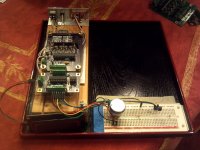
Put together a set of boards from the latest prototype. The haystack of earlier prototypes is gone, everything works, a little hardware optimizing remains, but very trivial.
Software is done except for improving the rotary encoder utility. That'll be ongoing, but one or two things need to be added now.
Software is done except for improving the rotary encoder utility. That'll be ongoing, but one or two things need to be added now.
Attachments
P.S. - in an automated production environment, I'd be more concerned with the off-center location of the OSHPark holes rather than their size.
I was rather surprised to see that, too.
I'm wondering if that is an artifact from your PCB Layout-to-Gerber converter? I've done dozens of boards with OshPark (and other proto houses) and never saw anything like that. I do a lot of fine pitch (12.5mil pin centers) SMT ICs with a 1 mil annular ring on the solder mask and the registration is dead on. Same with the drill file.
I've also not experienced the types of problems dchisholm writes about. All of the PCB fabs I've used (about a dozen total) assume hole size is finished (plated) size and they are always very close. But as he suggests, always best to stipulate that to the board house, especially if you are submitting boards for the first time.
BTW, the project is looking good.....
PS. Not too many automated houses out there for thru hole parts anymore, certainly not for the volumes you are looking at.
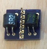
I've tried to think of the best way to mount LDRs on the board without requiring soldering by the end user, and came up with the carrier in the picture. The LDRs hang below the board on either side of the female connector that the male pins plug into. This is the only way I can keep the height of the LDRs down. Seems to work well . . .
Attachments
Well, on initial view it looks like a good idea but it does add some extra mechanical connections between the signal source and the LDR and this has been mentioned over the years as a source of signal degradation (ref: GeorgeHiFi and input selector switches, etc)
I built one of my 'kits' with the ldrs directly on the input & output phono sockets (no signal wires) and thought it provided a more dynamic result and never had a reason to change it so can't say if this direct connection was the reason, or not.
Uriah's LighterNote uses a separate pcb for the ldrs (early edition?) and uses terminal block connectors for the signal wires and it works flawlessly, particularly when used to vary/play with the loading impedances - didn't think to try a direct ldr connection to the phono sockets with this kits either so not too sure about the relevance of a simpler wiring scheme altho George is pretty emphatic about the benefits of simpler connections - perhaps this is something we could look at witrh the beta testing ....
I would suggest you actually mount the devices yourself using suitable heatsink clamps etc and add a cost/fee for the service if you're going to supply this unit as a kit - it would make it easier with this header board to perform final quality control testing but wiould see if there's some way to reduce the number of mechanical/electrical connections between the signal wiring and the ldrs trgemselves.
Personally, I would suggest you go the same way as Tartuga with value added, finished, tested modules and if the volume exceeds your capability, then outsource some of the assembly and just do the final ldr assembly, testing, etc to maintain quality control.
Nearly there ...
You could do what I do and solder in 2 x 8 pin gold flashed dil sockets, this lets you push in and remove them if some are what I call "mad ones", then once your happy all is fine they can be soldered into the sockets very easily with a fine hot tip.
Cheers George
Cheers George
Well, on initial view it looks like a good idea but it does add some extra mechanical connections between the signal source and the LDR and this has been mentioned over the years as a source of signal degradation (ref: GeorgeHiFi and input selector switches, etc)
I built one of my 'kits' with the ldrs directly on the input & output phono sockets (no signal wires) and thought it provided a more dynamic result and never had a reason to change it so can't say if this direct connection was the reason, or not.
Uriah's LighterNote uses a separate pcb for the ldrs (early edition?) and uses terminal block connectors for the signal wires and it works flawlessly, particularly when used to vary/play with the loading impedances - didn't think to try a direct ldr connection to the phono sockets with this kits either so not too sure about the relevance of a simpler wiring scheme altho George is pretty emphatic about the benefits of simpler connections - perhaps this is something we could look at witrh the beta testing ....
I would suggest you actually mount the devices yourself using suitable heatsink clamps etc and add a cost/fee for the service if you're going to supply this unit as a kit - it would make it easier with this header board to perform final quality control testing but wiould see if there's some way to reduce the number of mechanical/electrical connections between the signal wiring and the ldrs trgemselves.
Personally, I would suggest you go the same way as Tartuga with value added, finished, tested modules and if the volume exceeds your capability, then outsource some of the assembly and just do the final ldr assembly, testing, etc to maintain quality control.
Nearly there ...
James, I truly appreciate your thoughtful and constructive comments!
With regard to the number of mechanical connections, I take your point but this is not a simple solder-it-and-play board and some connections are inevitable in the signal path for the following two reasons:
1. To calibrate, it is necessary to disconnect the input/output wires and connect the calibration circuitry. That requires a non-soldered connection that can easily be moved. That means a relay or a jumper system. I chose a gold-plated jumper system for the purists in the audience, with the option of installing a relay-based semi-automatic calibration solution as an option using the same connectors as the manual jumper plug (which is why I put the LDRs under the daughter board to keep the height down). That might be attractive
2. I would prefer a plug-and-play LDR daughter board that would allow an end-user to simply unplug a deteriorating LDR module and plug in a new one in just a few minutes without soldering. Replacing a module followed by a 15 minute calibration cycle means you could be up and running with new LDRs in very short order and maintain your board without soldering skills.
Those requirements are driving my choices. If I've got something wrong, I'd very much like to hear opposing views. But not everyone wants to deal with a soldering iron to maintain their LDR-based preamp, and the jumper-based play-calibrate system means that you literally cannot run the calibration program with the I/O connected, and you cannot run the play program with the jumper in the calibrate position because the location of the jumper controls what the computer allows itself to do and if the jumper is in the wrong position, the hardware/software will simply refuse to cooperate. That also insures that you don't send calibration voltages down the line to the power amp with possibly unfortunate consequences because in calibrate mode the I/O is entirely disconnected.
I always intended to sell the LDR daughterboard as a complete module with LDRs already installed.
Now, I've already caught myself making inappropriate compromises for the sake of making the board smaller, and I've had to back up sometimes and maybe I'm in that situation now. I could do a daughter board with pins to fit in a screw-down terminal block if I added maybe 1/2 inch to the length of the board. Would that be a better choice than what I've done here? Maybe, and I'll be looking at that again before I finalize.
I have been following your topic for quite some time now.
The idea of using LDR without any wiper contact or switching contacts as used at relay based resistor network seems to be beneficial.
It also seems that the variable gain is favorable compared to throwing away signal as is done by conventional volume control.
Based on your topic I made this variant: http://www.diyaudio.com/forums/analog-line-level/267600-pre-amp-2-stages-adjustable-gain.html
Although you are already really close to your final implementation I was wondering if you ever considered using 2 stages of attenuation avoiding pushing the LED's to higher curents to achieve low enough resistance ?
I have been following your topic for quite some time now.
The idea of using LDR without any wiper contact or switching contacts as used at relay based resistor network seems to be beneficial.
It also seems that the variable gain is favorable compared to throwing away signal as is done by conventional volume control.
Based on your topic I made this variant: http://www.diyaudio.com/forums/analog-line-level/267600-pre-amp-2-stages-adjustable-gain.html
Although you are already really close to your final implementation I was wondering if you ever considered using 2 stages of attenuation avoiding pushing the LED's to higher curents to achieve low enough resistance ?
What an interesting idea, I wish you well in making it happen. Having been through the wringer on my own version of this, I know without doubt that the devil is going to be in the details and is going to be much less than easy.
Some of the main challenges are:
1) To use a standard linear ADC with 1023 levels (10 bits) to control a logarithmic LDR from, say, 40 ohms to 10K ohms. If you lay out the graph you will see that the LDR will eat up 900 of those 1023 linear counts going from 40 ohms to about 200 ohms on the log scale, leaving you with about 100 counts to control the entire range from 200 ohms to 10,000 ohms. You can do it, but with very poor resolution. You really need 12 bits of resolution 4096 counts) or better, so you need a way to come up with 2 more bits of resolution, minimum, from what is essentially a 10-bit PIC.
2) To design a power management system that provides precision control over a range of about 10 milliamps down to about 3 micro-amps with 2 micro-amp resolution at the low end. That's really hard, or at least it was for me. BTW, 10 ma is my absolute maximum current driving an LED that is rated for 25ma; I think of it as quite conservative and don't expect LDR deterioration from excessive current. And that's at 'minimum' volume, at normal listening the current will be 2 milliamps or less per LDR.
I'm not sure what folks will say about using two op-amps in the circuit because ostensibly one of the benefits of the LDR solution is that it is a truly passive preamp. I don't know about the value of that, but for sure my passive LDR control certainly has improved the sound of my admittedly mediocre sound system.
Early on, James Hill made me look at how much attenuation was truly needed given the passive (no gain) nature of the LDR preamp, and while at first I was doubtful I now believe that he is right -- 50dB is plenty of attenuation for most systems. I myself am now using a 50dB attenuating LDR pot, and it's plenty. In fact, it's the first time I've ever owned an audio system where I could truly use the entire rotation range of the volume control -- from very low level to blasting hot at the high end -- and I really like it. I've always had systems where I normally used 8 o'clock to 10 o'clock for normal listening and 12 o'clock to blow my eardrums out. Most of the gain was never used. So, if you have to make sonic compromises in order to achieve high levels of attenuation, it might not be worth it in my opinion.
But, you know, people were scoffing at me early on when I started talking about the results I was getting but I got here eventually so certainly it can be done. Again, I wish you well.
- Status
- Not open for further replies.
- Home
- Source & Line
- Analog Line Level
- A precision LED/LDR-based Attenuator