Glad you sorted it out Doede. I wonder why 5v works fine on J3 on my fifo and not on your’s.
Maybe Leif shall try the same as you did, and perhaps his fifo will work too.
Anyway, happy new year to all dddac users. 🙂
Maybe Leif shall try the same as you did, and perhaps his fifo will work too.
Anyway, happy new year to all dddac users. 🙂
I see that smooth dancer only connects power to J3, this is one reason why Doede....needs investigating 🙂
I think you may have seen an old picture Simon. If you look closer you will see that there is two wires from dddac mainboard , 5v and gnd, which goes to pin 2 and 6 on the 40 pin J7.
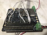
I ended up with two 5v psu’s. One for J5 on fifo, and the other for waveio and J3 on fifo. If you do it like Doede did it, you need only one psu for the isolated side, and that’s the one from i2s output on mainboard to J5 on fifo. Your dddac 5v psu take care of waveio and J3. BUT, if you run into trouble as Doede did, you must copy what he did with the 18 ohm resistor before J3.
Since I have already built and everything play’s great, I will leave it as it is.
I recommend to do it like Doede did, Simon.
Last edited:
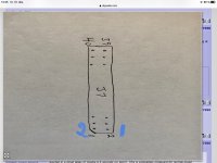
You've got the numbering wrong: all odd numbers are on one side of the connector, evens on the other
OK but the cut out on the connect edge normally indicates pin 1. So where is PIN 1 please?
I think you may have seen an old picture Simon. If you look closer you will see that there is two wires from dddac mainboard , 5v and gnd, which goes to pin 2 and 6 on the 40 pin J7.
I ended up with two 5v psu’s. One for J5 on fifo, and the other for waveio and J3 on fifo. If you do it like Doede did it, you need only one psu for the isolated side, and that’s the one from i2s output on mainboard to J5 on fifo. Your dddac 5v psu take care of waveio and J3. BUT, if you run into trouble as Doede did, you must copy what he did with the 18 ohm resistor before J3.
Since I have already built and everything play’s great, I will leave it as it is.
I recommend to do it like Doede did, Simon.
Yes I see those wires now and all makes sense now. I will make mine like Doede has
OK but the cut out on the connect edge normally indicates pin 1. So where is PIN 1 please?
Normally this is correct Simon, but on fifo it is opposite.
Me again 🙂
Ref the PIN numbers on the 40pin connectors for the IAN. I thought the numbers were as in my diagram but looking at peoples pictures I see a wire attatched to PIN 40 as expected but then counting back does not align, what am I missing...if anything and its just me?
Dont want to make mistakes
Thanks
Swap 1 and 2 . 40 and 39 is correct.
Normally this is correct Simon, but on fifo it is opposite.
Crazy to go opposite the standards and could cause serious issues
Obs...
Thanks its now clear
 , picture speaks a 1,000 words and why I like to document my work 😀
How I connected the Connectors.... 🙂
Attachments

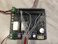
How I connected the Connectors.... 🙂

 😀 nice and clear
18 ohm resistor still required?
18 ohm resistor still required?
Yes, without it does not work 😕
On the pic you see the connections before I added the 18 ohm, sorry...😱
Yes I see those wires now and all makes sense now. I will make mine like Doede has
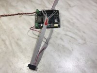
So When you play with a WaveIO and the way I did it, you do not need any extra power supply....
What value for a choke ? It depends on rest of the psu design. Smaller chokes cost less and is easier to implementing in a given cabinet size. I use the Lundahl 1694. You can order directly from Lundahl, or maybe there is a dealer in the UK ?
I know eduard is a fan of big chokes, but how big is needed in a dac ?
Hello,
I started with the ll2733 ( which is the bigger brother of the ll1694) The bigger the number of mH the less current you need to make it work like a true choke input.
Doede himself simulated the latest supply i build using the ll2771 which offers 3000mH at 1A so can be used with a 4board dddac like i am using.
Connecting it in common mode as pictured in the pdf from lundahl is the best way.
Of course you will need a higher ac voltage in with this choke because dcr is higher than the other lundahls but it will filter better too.
At the time i start using it i did not know about how much ac voltage i need so i bought a lundahl with many secundairy windings so i can compose the right voltage easily.
Not sure if the Triad split bobbins are available in the right ac voltage output.
DON'T care at all if the transformer is only rated for 2A at the desired voltage. The energy drawn by the load is held at a constant current so it will not heat up like usually happens when there is a capacitor input which is charged in pulses.
As you can see in my previous posts the diodes can be smaller than usual too because they are not heated up by pulses constantly.
Just give it a try and tell us you are sorry you did not try this simple modification before.
Greetings, Eduard
P.s but remember the ll2771 is big and heavy but compared to the other chokes by lundahl they offer much greater value ( mH) for the money spent.
Yes, without it does not work 😕
On the pic you see the connections before I added the 18 ohm, sorry...😱
Dont say sorry, its clear 🙂
So When you play with a WaveIO and the way I did it, you do not need any extra power supply....
Love it! 😀 Makes sense
Feel free to send presents soon 😛. Feb 5th 1960 ...
😀 haha I soldered the FiFo Connectors so i could do an easy and quick change of the flat cables for comparison 😎
I have many of those jumper cables and use them a lot for Arduino projects !
Last edited:
@Doede
I see on your pictures that you have 6 wires on J7. Do you have one gnd wire for each i2s signal wire ? I’m asking because I only use one gnd wire for the i2s signal wires (it work’s fine with one gnd wire). But I don’t see a gnd wire for i2s on J1, only wires from dddac mainboard for i2s signals, + 5v and gnd.
I’m asking because I’m still learning. 🙂
Hello,
I started with the ll2733 ( which is the bigger brother of the ll1694) The bigger the number of mH the less current you need to make it work like a true choke input.
Doede himself simulated the latest supply i build using the ll2771 which offers 3000mH at 1A so can be used with a 4board dddac like i am using.
Connecting it in common mode as pictured in the pdf from lundahl is the best way.
Of course you will need a higher ac voltage in with this choke because dcr is higher than the other lundahls but it will filter better too.
At the time i start using it i did not know about how much ac voltage i need so i bought a lundahl with many secundairy windings so i can compose the right voltage easily.
Not sure if the Triad split bobbins are available in the right ac voltage output.
DON'T care at all if the transformer is only rated for 2A at the desired voltage. The energy drawn by the load is held at a constant current so it will not heat up like usually happens when there is a capacitor input which is charged in pulses.
As you can see in my previous posts the diodes can be smaller than usual too because they are not heated up by pulses constantly.
Just give it a try and tell us you are sorry you did not try this simple modification before.
Greetings, Eduard
P.s but remember the ll2771 is big and heavy but compared to the other chokes by lundahl they offer much greater value ( mH) for the money spent.
Thanks Edward
I did build a choke PSU for my main DAC now playing with another DAC build.
I remember my first choke PSU was very difficult to get the transformer voltage and bleed resistors correct to get the 12v needed to fed the DAC
- Home
- Source & Line
- Digital Line Level
- A NOS 192/24 DAC with the PCM1794 (and WaveIO USB input)