I think it is important to separate 5v from waveio and 5v out from mainboard. If not, waveio will be on the same side of the fence as fifo’s isolated side. I only connect the i2s lines +gnd from J7 - i2s mainboard. J7 have dedicated 5v psu.
Doede, can you confirm if my thoughts about 5v between waveio and 5v on mainboard are correct ? As I see it, only i2s lines + gnd, from J7, shall be connected to mainboard, and fifo powered by a clean psu (J-5 header).
we are aligned that waveio and Mainboard should be separated by the IAN...
Now the 5 Volt for the FIFO (J5) can be separate, or coming from the LF50 (10 pin header) from the mainboard (must be cooled than)
Ok so to be totally clear ...
Waveio has its own 5v PSU and the Ian also has its own 5v PSU. So which 5v powers the waveio isolator?
Waveio has its own 5v PSU and the Ian also has its own 5v PSU. So which 5v powers the waveio isolator?
@Simon
It looks perfect. Just hook up and enjoy.
Thanks for your help 😀
Ok so to be totally clear ...
Waveio has its own 5v PSU and the Ian also has its own 5v PSU. So which 5v powers the waveio isolator?
J2 on fifo. J3 header,or pin 2 and pin 6 on J2. You can use the same 5v power as waveio use.
Ok,
We will wait for the first reports to appear. First step will be using the Aurender with some new circuits added to the wave io.
Going for the Roon could be the next step.
Greetings, Eduard
We will wait for the first reports to appear. First step will be using the Aurender with some new circuits added to the wave io.
Going for the Roon could be the next step.
Greetings, Eduard
Yes,diy + doede psu for regulation.
Could you explain the reason for the PSU changes and the benefits of the chokes?
I can understand some changes are to deliver the current needs
Thanks
A choke block higher frequencies, and makes life easier for the other components to fight ripple in a psu.
A choke need a bleeder resistor (after the choke) for optimal functionality.
I put chokes in my psu because I want to maximise where I can, and since it is diy it’s not expencive and just pure fun.
Doedes stock psu is very good too. I have’t been doing a comparason, but a friend of mine use stock Doede psu’s on his dddac, and it sounds very good.
Doede’s stock psu deliver enough current if you don’t stack more than 4 boards.
Last edited:
What value for a choke ? It depends on rest of the psu design. Smaller chokes cost less and is easier to implementing in a given cabinet size. I use the Lundahl 1694. You can order directly from Lundahl, or maybe there is a dealer in the UK ?
I know eduard is a fan of big chokes, but how big is needed in a dac ?
I know eduard is a fan of big chokes, but how big is needed in a dac ?
I have the 1694 in my main DDDAC based on Edwards design. Building a second dac using standard psus and wanted to try what what you have done
Do you have a diagram so it’s clear? I found a UK dealer
Do you have a diagram so it’s clear? I found a UK dealer
Sorry, no diagram. It’s been a long time since I put it together, but do as I did, use Duncan’s psu designer, and you will end up with a good psu in the end.
From my memory; I use R-core trafo’s (300va) Toroidal is nice too, and easier to buy. The trafo’s don’t need to be so big. (I have my R- core already in house).
Sjøstrøm rectifier bridges, Mundorf M-Lytic caps ( 20000uf-10000uf), and wirewound (bleeder)resistors.
When you play with Duncan’s psu designer you must try to end up with around 20v before dddac’s 12v psu, and 12-15v on dddac’s 5v psu. 7-10v for regulation is ok without the regulator on dddac psu get’s to hot.
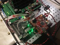
Ian FIFO problem - and.... solved
Need to share this right now...
The Ian was NOT working till for 10 minutes ago. I was very frustrated yesterday evening as the FIFO status LED stayed red (empty buffer). I had to sleep a night over this - ask a few fellow DIY and even thought the board could be defective (already ordered a new one 😀 this one will stay for a RoPIeee server next to build 😛 )
today I had the smal lightbulb flash and tried with a lower voltage on J3, the connector for the power supply input for the not-isolated INPUT side of things and where all the controlling is happening. My idea was that the PI works with 3,3 V logic and maybe this was the issue, that the 5 Volt I am taking from the Waveio was too much and the 5V logic I2S signals were not working correctly. Well indeed...……
NOW it all works perfectly well between roughly 3 and 4 volt on J3 (J5 stays 5 volt from the mainboard at the isolated side to be 100% clear)
Now to avoid an extra 3,3 Volt power supply just for the controlling side of the Ian FIFO I still take the 5 Volt from the Waveio but with a 18 Ohm / 1 Watt resistor in series to arrive at 3,34 Volt at J3 (The current draw is pretty constant between 85mA and 90mA depending on FS 44.1 - 192kHz)
As this makes the earlier "recommendations" basically wrong, I wanted to post this ASAP... Listening tests I will do tomorrow 😎
FYI:
J3 - 3,34 Volt draws 87mA in average - no problem for the 5Volt supply for the Waveio
J5 - draws (only) 24 mA. This comes from the LF50 on the DDDAC Mainboard and hence does NOT require any extra cooling (I am trying right now as I type this - stays below hand warm)
sorry for wrong Infos based on "logical" thinking, which turned out to be not so logical 😱
For tomorrow….. Happy new year evening to all of you and make sure after the fireworks you still have your fingers to do all this nice DIY 😀
Does the IAN FiFo introduce a delay in the sound output, similar as the Kali? The data buffering in the Kali resulted in a small delay of maybe 0.5 seconds (or less?). This is completely irrelevant for normal music listening, but if you also want to use it for movies, the delay is quite annoying. It would be interesting to know if the IAN board does the same, and how much the delay is.
Need to share this right now...
The Ian was NOT working till for 10 minutes ago. I was very frustrated yesterday evening as the FIFO status LED stayed red (empty buffer). I had to sleep a night over this - ask a few fellow DIY and even thought the board could be defective (already ordered a new one 😀 this one will stay for a RoPIeee server next to build 😛 )
today I had the smal lightbulb flash and tried with a lower voltage on J3, the connector for the power supply input for the not-isolated INPUT side of things and where all the controlling is happening. My idea was that the PI works with 3,3 V logic and maybe this was the issue, that the 5 Volt I am taking from the Waveio was too much and the 5V logic I2S signals were not working correctly. Well indeed...……
NOW it all works perfectly well between roughly 3 and 4 volt on J3 (J5 stays 5 volt from the mainboard at the isolated side to be 100% clear)
Now to avoid an extra 3,3 Volt power supply just for the controlling side of the Ian FIFO I still take the 5 Volt from the Waveio but with a 18 Ohm / 1 Watt resistor in series to arrive at 3,34 Volt at J3 (The current draw is pretty constant between 85mA and 90mA depending on FS 44.1 - 192kHz)
As this makes the earlier "recommendations" basically wrong, I wanted to post this ASAP... Listening tests I will do tomorrow 😎
FYI:
J3 - 3,34 Volt draws 87mA in average - no problem for the 5Volt supply for the Waveio
J5 - draws (only) 24 mA. This comes from the LF50 on the DDDAC Mainboard and hence does NOT require any extra cooling (I am trying right now as I type this - stays below hand warm)
sorry for wrong Infos based on "logical" thinking, which turned out to be not so logical 😱
For tomorrow….. Happy new year evening to all of you and make sure after the fireworks you still have your fingers to do all this nice DIY 😀
This is very strange. be interesting to read if the others that have built the IAN have the same issue Doede.
Happy New Year too! 😀

I see that smooth dancer only connects power to J3, this is one reason why Doede....needs investigating 🙂
Me again 🙂
Ref the PIN numbers on the 40pin connectors for the IAN. I thought the numbers were as in my diagram but looking at peoples pictures I see a wire attatched to PIN 40 as expected but then counting back does not align, what am I missing...if anything and its just me?
Dont want to make mistakes
Thanks
Ref the PIN numbers on the 40pin connectors for the IAN. I thought the numbers were as in my diagram but looking at peoples pictures I see a wire attatched to PIN 40 as expected but then counting back does not align, what am I missing...if anything and its just me?
Dont want to make mistakes
Thanks
Attachments
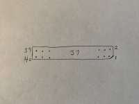
You've got the numbering wrong: all odd numbers are on one side of the connector, evens on the other
His previous version did and any buffered solution will. It was around the same as Kali ie 0.5s and annoying with dialogueDoes the IAN FiFo introduce a delay in the sound output, similar as the Kali? The data buffering in the Kali resulted in a small delay of maybe 0.5 seconds (or less?). This is completely irrelevant for normal music listening, but if you also want to use it for movies, the delay is quite annoying. It would be interesting to know if the IAN board does the same, and how much the delay is.
- Home
- Source & Line
- Digital Line Level
- A NOS 192/24 DAC with the PCM1794 (and WaveIO USB input)