They are the ones by the music outputs of the mainboard, should be 4 of them, marked rload, ra and rb. Or just measure the Ohms on the outputs between pos+common and neg+common on both channelstrying to work out which the I/V resisters are, once I have I will let you know the value and the reading I get with the multi meter.
Ok, it's possible that is your issue. The rload resistors are there to convert the current output of the dac to a voltage output. The required values of these resistors vary depending on the number of dac decks you have. I think the main board kits are usually supplied with resistors for 1 deck which will be around 133ohm. If you have 2 decks, you will want these resistors to be around 68ohm instead.I see. In that case they are reading 125.0Ohms
Ra and Rb connections go to and from the same place and are in parallel, so you could add more resistors of the same value to the Rb points to give the right values, or take out the Ra ones and replace.
See the bottom of page 3 here.
http://www.dddac.com/documents/dddac1794s_nos_ver42.pdf
Does that make sense?
Hi Doede,
don't get me wrong, it is just an experiment.. your design work's perfect.. also with IAN's FIFO connected via I2S .. it sounds fantastic.. IMO best DDC solution compared to Wave IO, Amanero and JL Sounds.
Additional I want to try to feed the DAC boards directly from IAN's additional I2S to PCM board .. it's just an experiment and i would share the result here because some users may be also interessted.
btw.. Output Format of I2StoPCM attached.
ok, got it. This will not work, as the dac boards do not take PCM format. It is standard right handed 24 bit. see datasheet of PCM1794a. will you be able to output that of the board?
This what you have is for PCM63 and that kind of chips
fantastic, if it turns out to be the rload resister value I will be a very happy man!
I worked out the existing resisters are Vishal 133k 1/8w resisters. I cant easily get hold of these to add to the existing ones so will replace with 68k resisters.
looking on the hifi collective website the best match would be 68k 0.5w resisters, I assume these will be fine?
Dose anyone have experience of different makes of resisters at the I/V, is it worth going for something like the Audio Note Tantalum Non-magnetics Resistors?
fantastic, if it turns out to be the rload resister value I will be a very happy man!
I worked out the existing resisters are Vishal 133k 1/8w resisters. I cant easily get hold of these to add to the existing ones so will replace with 68k resisters.
looking on the hifi collective website the best match would be 68k 0.5w resisters, I assume these will be fine?
Dose anyone have experience of different makes of resisters at the I/V, is it worth going for something like the Audio Note Tantalum Non-magnetics Resistors?
It is 68 ohm not 68k....
Does someone have an experience with Lampizator dac and the Dddac. I am trying to figure out what change it will be if i exchange my L4 with dddac. I would appreciate any comments.
search for my post on this thread comparing Lampi 7 to DDDac. DDDac compared very favourably!
You can also use tube buffer output. I tried it and it sounded great, but in the end I went for the JFET buffer output as i couldn't get it all in my case
Juancho that is a big statement. Great news! Do you think dddcc can compete with good vinyl setup? My idea is to build a dac with 101 tube output. I experimented with different dacs and tube output and liked the result. Yes it is rather spacious solution. What was your dddac configuration?
DDDac config is separate analogue and digital choke regulated psus, JFET buffer output stage with separate psu, separate psu for Wave board. Caps upgraded to Panasonic Fcs in psu, the special PEPs for digital filtering along with Black Gates. I see a lot of top vinyl rigs in my upgrade business. I can't say vinyl or DDDac is better as even the sae album has different mastering. But in tests folk sometimes prefer the vinyl, sometimes the DDDac and we're talking some very expensive rigs
Hi
someone tried the jfet buffer with 4deck,,,with and without trafo.
I will try the buffer with my 4deck,,without My Sowter trafo..but will take some time
how importent is the matching of the BF862 ?
Best Bjarne
someone tried the jfet buffer with 4deck,,,with and without trafo.
I will try the buffer with my 4deck,,without My Sowter trafo..but will take some time
how importent is the matching of the BF862 ?
Best Bjarne
I wish i could here it. This is crazy anyway) Thank you Juancho! I will give it a try. Need to wait for the new boards to come. Could you tell me what tube output you made and how did it compare sonically to JFET buffer?
I wish i could here it. This is crazy anyway) Thank you Juancho! I will give it a try. Need to wait for the new boards to come. Could you tell me what tube output you made and how did it compare sonically to JFET buffer?
I used a simple anode follower loosely based on the Lampizator design on his site. I can't really say how the two compare. I would have been happy with the tube buffer but there was n room in my case. The jfet takes several hundred hours to come on song.....as you know my dddac spec compares very favourably with a Lampi 7 I upgraded and which was using the uber expensive KR Audio WE replica valves and rectifier, so around £10,000 of Dac. My Dac came in inc. its lovely Italian case around a £1000.........
Teaser 😉 😛
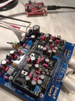
Received the boards back from the SMD assembly house and built yesterday evening the first production DAC. See image... Everything worked right away, so I am a happy man 😎
Audio Creative will have all boards and parts for kits next week hopefully (depending on DHL) so the new dac modules will be available very soon now.
I was lucky with the FET batch (bought 1000 pcs for 500 dac boards, so we will be good for some time). With the standard position of the trimmers and this batch, the DC bias was at cold start 38mV, so very close without adjusting (!) to the required 40mV. Meaning at switch on, the DAC was playing right away correctly. I tuned to 40mV after half an hour warming up.
Just FYI.... Current consumption of one DAC module is now round about 210mA (due to the TENT shunt regulator taking some extra current of course)
The standard power supply from DDDAV will be ok for 4 decks so to speak.
Attachments
- Home
- Source & Line
- Digital Line Level
- A NOS 192/24 DAC with the PCM1794 (and WaveIO USB input)