I don;t know specifically about Ian's reclocker, but it has proved possible to use something like the BBB Botic driver to output the 2 data channels for left and right in the correct format for the deck boards and therefore do without the main board. I am very interested in this, but I have yet to try it
I try to run the DDDAC with IANs PCM Baord with no luck. Sound comes out but with heavy noise 🙁 I guess littel disaligment of the clock or LR signal..
Did you study what comes out of ian's board? Did you connect it to the main board i2s or did you experiment with straight to the dac board it self ?
Did you study what comes out of ian's board? Did you connect it to the main board i2s or did you experiment with straight to the dac board it self ?
I experiment to feed the DAC boards directly via IAN's I2S to PCM board.. but no with no luck 🙁
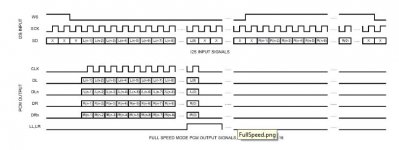
So what are they supposed to output? What did you tell the Ian board to do so to speak?How did you connect it? Small drawing may be or pics ? The DAC boards need 24 bit right handed I2S delayed 32 bits on one channel. Is that what the Ian board outputs?
Oh, just to make sure, it is ok to experiment with my boards or designs, no discussion. But if you want a proven working, good sounding concept, just use my mainboard with the DAC modules. They were suppose to work together and are adjusted to each other. Any thing else is really DIY...
any progress about new boards? i check audio creative's site frequently, no news about the new boards...
Hello,
You could subscribe to their newsletter. I am sure when boards are available they will write about it in their newsletter. After all they are in for the money.
Of course Doede will also be informed and the news will pop up here too.
Maybe the first batch ( if i am right i read somewhere it will be 100 boards) will be sold within one week. Just a few people needed that want to build a 4 board dac ( like myself) and 100 boards are gone soon.
Maybe just wait for the first reactions and start buying with the second batch.
Greetings, Eduard
Boards are at the SMD assembly company 🙂any progress about new boards? i check audio creative's site frequently, no news about the new boards...
Expect them back end this week or beginning next week. Than kits need to be made ready and made available...
Hi!
2 months ago i tweaked my DDDAC with the CCS-boards and the tentlab-shunts for the analog side. i have 3 decks and was quite happy. but today, it made a little plopp and now the left channel is louder than the right (both play music). i messured the output of the right channel and between neg-pos there is .0.9 DC, between neg-GND 1.8DC and between pos-gnd it is 2,7 DC.
any ideas for help?
thanks, mario
Hi!
2 months ago i tweaked my DDDAC with the CCS-boards and the tentlab-shunts for the analog side. i have 3 decks and was quite happy. but today, it made a little plopp and now the left channel is louder than the right (both play music). i messured the output of the right channel and between neg-pos there is .0.9 DC, between neg-GND 1.8DC and between pos-gnd it is 2,7 DC.
any ideas for help?
thanks, mario
Sure, please check if all chips has the right voltage supply. And look for bad connections between the 3 decks
Last edited:
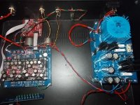
Hello everyone. I asked for some help fault finding last week and received a response from a couple of members, see below.
After testing the voltage from the two power supplies I now realise the 12v was actually reading 25v so I am guessing I have fried something or everything? In my defence the 12v was brought as a built and tested 12v supplied so I didn’t check the voltage. Anyway a lesson learnt.
I tested the positive and negative outputs from the mainboard all read 2.48v
The dac boards read the same on both sides:
BCK 2.44v
Dat nothing
LR 2.49v
And on the other side of the dac boards the positive and negative (A and B) all read 2.49v
The output (RCA) I am getting a reading of 00.4v
Sorry about the lack of any technical terminology but I am learning and starting from a very basic point so I would really appreciate responses to be as basic as possible.
Thanks in advance!!!
Measure the DC voltages at the output - disconnect the transformers first. Ensure the symmetrical DC reading of around 2.5V is present on either channel.
It seems that as you change the loading by turning the pot, the sound cleans-up, as you said. so check the I/R resistors connections and the output transformers orientation and connections.
Check the Iref voltage as well - this will tell you if the Vcc's are okay and if the DAC IC's are okay.
The fact that you are using S/PDIF input, and the fact that you are not getting light from the sampling frequency LED's tells me that your motherboard soldering might be bad / oscillator is not connected properly, or the voltage regulation is off.
DAC IC's might get damaged if you power up the DAC boards with no clock present at DAC inputs - either from XMOS, or from 8804 receiver.
So, a bit of faultfinding seems to be in order. This information is also available on Doede's website
Good luck,
Nick
thanks a lot doede! just a broken connection between the decks at the output.
as "suspected". Thanks for posting back. It will add to the community's "database" of things to look after when something is not working properly 🙂
Sorry I should have said in the last post that I need guidance as to how to further locate the fault and how to fix it, or at worst whether I should cut my losses and buy a new mother board and dac boards, in which case which components should be OK from the old boards to use in the new.
thanks again
thanks again
So what are they supposed to output? What did you tell the Ian board to do so to speak?How did you connect it? Small drawing may be or pics ? The DAC boards need 24 bit right handed I2S delayed 32 bits on one channel. Is that what the Ian board outputs?
Hi Doede,
don't get me wrong, it is just an experiment.. your design work's perfect.. also with IAN's FIFO connected via I2S .. it sounds fantastic.. IMO best DDC solution compared to Wave IO, Amanero and JL Sounds.
Additional I want to try to feed the DAC boards directly from IAN's additional I2S to PCM board .. it's just an experiment and i would share the result here because some users may be also interessted.
btw.. Output Format of I2StoPCM attached.
Attachments
Can you clarify how many dac boards you have and what ohms your i/v resistors are?Sorry I should have said in the last post that I need guidance as to how to further locate the fault and how to fix it, or at worst whether I should cut my losses and buy a new mother board and dac boards, in which case which components should be OK from the old boards to use in the new.
thanks again
If you're stuck, I don't think I'm too far from you and could help you do a quick sanity check of a few bits if you can wait a week or so for my work to quieten down a little?
If you can post some pictures up here of your current setup, that would help people point you in the right direction too.
Cheers,
James
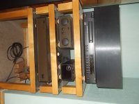
Thanks dwjames, you have no idea how grateful I would be for your help, where are you based? I brought the dac over a year ago so a few more week waiting wont make any difference.
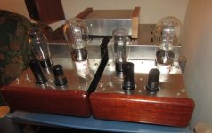
Anyway here are a couple of pictures for folk to look at.
The setup is basically two decks with components I received from audio creative including the cinemags as the output caps.
trying to work out which the I/V resisters are, once I have I will let you know the value and the reading I get with the multi meter.
Thanks once again
Attachments
- Home
- Source & Line
- Digital Line Level
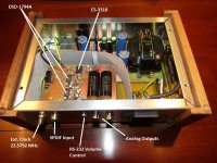
- A NOS 192/24 DAC with the PCM1794 (and WaveIO USB input)