Anyone?I'm thinking about beefing up my standard 12V DDDAC PSU ... is there any merit in increasing the big 4700uF caps (C1 and C3) to 10000uF? Can I do that alone or would I have to change other components to bring it back into balance?
It's quality more than quantity. Also, higher voltage capacitors will help as well. I settled on Elna Super Gold 3,300uF/50V for 12V DC supply, and on Elna Silmic II 3,300uF / 50V for 5V DC supply.
The other capacitors will need to be changed as well. Mixture of Black Gates, ELNA silmic Super Gold and Silmic II’s and SMD's worked very well for me. Major improvement. I compared it with choke loaded power supply, and the one I modified with capacitors sounded much better.
It's all part of the tuning process. The red WIMA's 0.1uF should be changed to SMD types… not only on the power supplies…
The DC rails’ (12 and 5V) noise can be measured as well… what measures good, does sound good as well (in this instance).
The transformers supplied with the kit are very good, except the 5V DC supply should have a bigger transformer that comes with 12V DC supply - it sounds so much better. Dissipation across the series transistor due to the higher voltage drop is not an issue, although it will run hot. I tried bigger transformers (also Talema, or something like that…), but in my system, the original transformers sound very nice. Other systems would probably benefit from bigger transformers, which emphasise bass and midrange more.
Nick
Thanks for your suggestions Nick - will give those a try - the SMD caps seem like a quick win.
In other news...
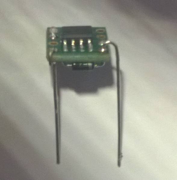
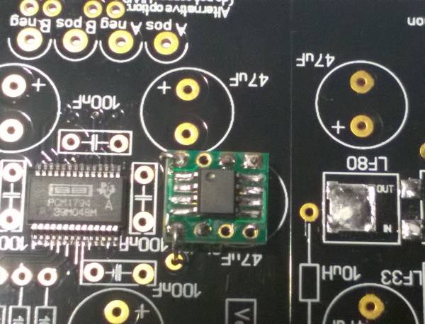
Been working on a CCS using the LM334M (as suggested somewhere earlier in this thread) here's some photos:


If you spot the deliberate mistake - you're wrong! There is no deliberate mistake. Any mistake is a genuine SNAFU on my part.
In other news...
Been working on a CCS using the LM334M (as suggested somewhere earlier in this thread) here's some photos:


If you spot the deliberate mistake - you're wrong! There is no deliberate mistake. Any mistake is a genuine SNAFU on my part.
Hello Doede,
I hope we will be able to be informed here once the boards are available to be ordered. Of course will send email to audio creative to keep me updated.
Greetings, Edward
I hope we will be able to be informed here once the boards are available to be ordered. Of course will send email to audio creative to keep me updated.
Greetings, Edward
Hello Doede,
I hope we will be able to be informed here once the boards are available to be ordered. Of course will send email to audio creative to keep me updated.
Greetings, Edward
Good idea.... Design is ready, prototype ... listening and technical tests past 🙂 I ordered yesterday 300 PCB so I can have first round of 100 boards SMD assembled end March. Than build a DAC to see if all is all fine and we can roll....
Do you have an idea how much more expensive these new boards will be yet Doede?
Do you have any plans to supply PCBs with smd components only or will they be always as a kit?
Do you have any plans to supply PCBs with smd components only or will they be always as a kit?
Do you have an idea how much more expensive these new boards will be yet Doede?
Do you have any plans to supply PCBs with smd components only or will they be always as a kit?
No price set yet, but as the Tent shunts are now on it they will be higher of course. Expect to have price set end of March when all cost of parts an d production cost are 100% clear.
To keep things simple and straight forward It will always be a kit.
Hello
Just like to know....is it only the motherboard ,,or is it also the dac board there will be new version of ?
Best Bjarne
Just like to know....is it only the motherboard ,,or is it also the dac board there will be new version of ?
Best Bjarne
I think is only the DAC board
Correct, it is the DAC board. The main board is still fully up to date 🙂
Hello,
I want to build to Dac to go with a TVC passive preamp to a 2a3 direct coupled amp to full range speakers.
I hesitate between the DDDAC1794 and the soekris R2R knowing that I listen mostly classical music. Any suggestion about what could be the best adapted ?
Jules
I want to build to Dac to go with a TVC passive preamp to a 2a3 direct coupled amp to full range speakers.
I hesitate between the DDDAC1794 and the soekris R2R knowing that I listen mostly classical music. Any suggestion about what could be the best adapted ?
Jules
Just an update on my DDDAC. It has been a long way coming and now I can rest assured this chapter of DDDAC considered completed. Don has also kindly helping me with the housing for my own diy DAC build! Without him, my DAC will get no where without such beautiful/professional finishes![emoji7]:thumb:
Massive Thanks to Don! [emoji322][emoji92]


Massive Thanks to Don! [emoji322][emoji92]


Last edited:
Thanks Guys!
Will upload more photos of the complete unit under operational later. 🙂
Sent from my iPhone using Tapatalk
Will upload more photos of the complete unit under operational later. 🙂
Sent from my iPhone using Tapatalk
Hello,
I want to build to Dac to go with a TVC passive preamp to a 2a3 direct coupled amp to full range speakers.
I hesitate between the DDDAC1794 and the soekris R2R knowing that I listen mostly classical music. Any suggestion about what could be the best adapted ?
Jules
Hi Jules - can't comment on the soekris R2R but I'm sure you wouldn't be disappointed with a DDDAC. Now I've only got my own DDDAC up and running in 'test mode' but even jury rigged as it is, I'm impressed by the natural and clear sound and immense detail retrieval I'm hearing.
So - everyone's getting excited about the new DAC boards - but I see they are some months away yet...
Meantime can someone confirm below is the right way to add Tent shunts to the existing DAC board. There seem to be a number of variations on this, so I've gone to the Tent Labs application note and come up with the following - apologies if this repeating something from elsewhere in the thread, but I looked and couldn't find anything.
First picture is the things to remove (in the red boxes), which are the existing VRs (A) and the output decoupling capacitors (B) - assuming you are fitting the shunts nice and close to the PCM 1794, the application note suggests you can fit the shunt as if it were the decoupling capacitor and also says the shunt boards have an output decoupling capacitor fitted on the board itself - so no need for extra capacitors.
Next are the things to add (shown below in blue), which are the 8V and 3.3V Tent shunts (C) and (D) and to note they are fitted as close as possible to the PCM 1794 feeding in at (E). I've added dropper resistors to both Tent shunts to bring the supply voltage toward the bottom of the specified supply voltage range, this should reduce the current draw and so reduce the heat generated and the PSU capacity required. Both these last things I was a bit concerned over as I'm building a 4 deck DDDAC using the standard Deode power supplies and it's all going to be a tight fit in the case. I've also added input decoupling capacitors for the shunts - the app note suggests 10uF, but as I seem to have some spare 47uF capacitors thought I'd use those instead.
I have just shown the left channel - the right will be the same of course. Just want to be sure I have the circuit right before I jump into building more DAC boards - comments please!
Last edited:
At all points E I will still leave at least 10uF Capacitors. it causes a nice soft start. Also I never have been able to actually hear any difference for putting a shunt in the digital side. Real A-B comparison with two identical DACs (except the 3,3 V shunt of course)
At all points E I will still leave at least 10uF Capacitors. it causes a nice soft start. Also I never have been able to actually hear any difference for putting a shunt in the digital side. Real A-B comparison with two identical DACs (except the 3,3 V shunt of course)
Thanks for your comments.
As I have the 3.3V shunts already I was going to go ahead with them. But I do have the opportunity during the process to do some A-B comparisons - so I'll let you know!
Regarding the 8V analogue supply: doesn't all the capacitance on the input side of the shunt provide a soft start anyway? I mean in the PSU and also C1 - C4 on the DAC board?
But if it is recommended still to have some extra capacitance on the output side would 1 capacitor do? e.g. per the following (mock up) where the shunt feeds in at C18 position and the capacitor is in C32 position. I'm thinking about linking the 3 vcc points closely together with some wire so the shunt output is as close as possible to the vcc inputs (using the position for the positive leg of the now omitted film capacitors). Also I would cut some tracks (C25 to C34 and C20 to C24) so the previous vcc tracks weren't making little loops, would that be advisable?
Or am I over-elaborating based on my poor understanding of how these things work!

- Home
- Source & Line
- Digital Line Level
- A NOS 192/24 DAC with the PCM1794 (and WaveIO USB input)