Member
Joined 2009
Paid Member
No - the problem for the 2A3 is actually worse when I delay B+ until the filament is hot. The filament will be at ground potential until it's Ck is charged. The grid is nominally at the input tube plate voltage or worse if the input tube is cold. Either way this results in a large current flow through the tube until operating conditions have settled. Worse case you have 480V across an OPT + tube with a resistance of 1k meaning nearly half an amp instantaneous.
Conceptually it's a feature of dc coupling. In an RC coupled amp there is a grid leak resistor to ground..
If B+ comes up first and then the heater the only thing preventing a large current spike is that the heater doesn't turn on instantaneously. Perhaps this is the saving grace for dc-coupled amplifiers ??
i never delayed B+ in any of my tube amp builds and never regretted not doing it...
even with B+ at the plates, the tube will not conduct until proper warm up of the
cathodes and or filaments happen....
this issue has been discussed to death here at diyaudio,
simply no proof that not delaying B+ can ruin your tubes....
i have never seen filaments fail even if overvoltaged,
i have more tubes fail from mishandling as if rolling on the table and into the floor....
still some tubes had their gettering flash washed out...
but those were tubes that had leaked over time...
you just had to get a fresh one and replace them....
for dc coupling you can use a neon NE-2 across grid and cathode,
or else use a diode....
Member
Joined 2009
Paid Member
Don't misunderstand me, I am not concerned about cathode stripping, but large current surge beyond tube rating.
How much can the tube conduct without the filament voltage applied?Don't misunderstand me, I am not concerned about cathode stripping, but large current surge beyond tube rating.
Member
Joined 2009
Paid Member
Jazbo8, I am seeing it like this: The filament starts out at ground, due to the presence of the cathode bypass capacitor. This cap will get charged up until the filament (and virtual cathode) is at the operating voltage, over 200V. The current to charge up the cap comes through the tube in a big rush when the filament is heated.
Without filament power, how does the current flow through the tube to charge up the cathode capacitor? Or what is the plate resistance with zero or very low filament voltage?
Member
Joined 2009
Paid Member
The concern arises when the filament becomes hot, not before. Then current is limited by the plate resistance. I don't know how much of a 'soft' turn on you get as the filament heats up - I've no experience with DHT's
I'm sure the turn on time is documented somewhere, but as AJT already mentioned, the delay HV turn on is good to have, but it's not really a requirement for the tubes (DHT or IDHT) except for certain transmitting tubes.
On more or less perminant builds I delay B+ and use damper diodes to bring it up nice and slow.
I have some older 2a3's that really need over a minute before their heaters fully come up. They're still good though.
I have some older 2a3's that really need over a minute before their heaters fully come up. They're still good though.
Jazbo8, I am seeing it like this: The filament starts out at ground, due to the presence of the cathode bypass capacitor. This cap will get charged up until the filament (and virtual cathode) is at the operating voltage, over 200V. The current to charge up the cap comes through the tube in a big rush when the filament is heated.
without any filament heated up,there is no tube conduction that can take place, ever....
if you want delays, use tube rectifiers or dampers....
Member
Joined 2009
Paid Member
Oh dear, I'm still not explaining it right judging by the responses. I'll try again.
Forget cathode stripping - it's a fallacy for most of the tubes we use. I'm not concerned about it so put this out of your head it has nothing to do with my concern/question.
Now turn attention to the 2A3 filament. With no power applied across the filament it is cold. The filament is powered with a dedicated transformer. The secondary winding of the dedicated transformer floats up and down with the filament at a voltage I will call the 2A3 cathode voltage.
Two scenario's
1) Power is applied and the B+ comes up first, the input tube and 2A3 are both cold so no current will flow through them. The grid of the 2A3 is pulled up to B+ by the plate load of the input tube. The cathode of the 2A3 is at ground and the 2A3 cathode bypass cap is not charged. After some time the filament gets hot and starts emitting electrons and the 2A3 conducts current. With the grid at B+ and the cathode at ground the tube is turned on hard and flows current to charge up the cathode bypass cap. This is a potentially bad situation because the anode-cathode voltage and resulting current flow are above the tube maximum ratings. After a short time the current charges up the cathode bypass cap, increasing the cathode voltage and reducing the current flow - eventually the amplifier reaches its stable operating points.
2) Now thing about reversing the power up sequence. Power is applied to the 2A3 filament but not the B+, which is intentionally delayed. The filament of the 2A3 gets hot and starts emitting electrons. But without any B+ applied there is no current flow. The cathode is at ground. After a delay the B+ comes up and the grid of the 2A3 is pulled up by the input tube plate load resistor but the 2A3 cathode is still near ground. Again, the tube turns on hard, there is a large voltage across the tube and a spike in current flow until the cathode bypass capacitor is once again charged up and the amplifier settles to its stable operating points.
So it doesn't matter if you delay the B+ or not, the tube has to charge up the cathode bypass capacitor and this stresses the tube.
Or does it ?
Last edited:
ok, in that case you can use a neon lamp, NE-2 to fix that...
i do that all the time when using dc coupling...
i do that all the time when using dc coupling...
I used to put in B+ delays but they always produced a pop as they triggered and I imagined that sudden current surge and what it might be doing to the valve. I now don't use +B delays and the amps come up much more gracefully without any surges or pops.
Most of my amps are DC coupled.
I wont be going back to B+ delays and can see no benefit to them in domestic amps - they were never used in commercial designs.
Shoog
Most of my amps are DC coupled.
I wont be going back to B+ delays and can see no benefit to them in domestic amps - they were never used in commercial designs.
Shoog
Member
Joined 2009
Paid Member
Moving on....
I've evolved the original schematic a little but keeping to the original concept as much as possible. One key change is a hybrid power supply. The SiC diodes and associated filter capacitor do the heavy lifting and a pair of paralleled hollow state diodes provide both a soft-start and work with a choke to provide ripple filtering for the B+.
I am preparing a list of bits to order so I can get on with a build; comments and advice are welcome 🙂
Attachments

Last edited:
Member
Joined 2009
Paid Member
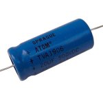
Anybody with experience/knowledge of Sprague Atom electrolytic ? - are they any good ?
Considering them for first filter cap as I have a bag of them. But I'm wondering if their 20uF 500V axial caps can take the ripple current from a solid state rectifier. I could put 3 or 4 of them in parallel to share the pain.
Considering them for first filter cap as I have a bag of them. But I'm wondering if their 20uF 500V axial caps can take the ripple current from a solid state rectifier. I could put 3 or 4 of them in parallel to share the pain.
Attachments
Good industrial quality caps that get the job done. If you've got them use them. They get the zen 'floobie dust' signature of approval from a couple of Japanese audio mystics. Take that as you will.
Personally I like oilers in the C1 position
Personally I like oilers in the C1 position
Last edited:
Anybody with experience/knowledge of Sprague Atom electrolytic ? - are they any good ?
Considering them for first filter cap as I have a bag of them. But I'm wondering if their 20uF 500V axial caps can take the ripple current from a solid state rectifier. I could put 3 or 4 of them in parallel to share the pain.
I have used them, old salvaged ones, and they seem durable. Thats the only comment I can offer.
Shoog
Why not use QUALITY capacitors ??
Every cap in a SE amp is IN the circuit. Use industrially priced, latest technology ultra wide band, lowest ESR WIMA DC LINK caps, for the supply.
I "tastefully" add film bypasses to each and every DC LINK, never go higher than 50 uF any where, and fully bypass them for maximum SE fidelity.
The Sprague ATOMS are way inferior......... comparatively.
Jeff Medwin
- Home
- Amplifiers
- Tubes / Valves
- A nice little valve amplifier