Member
Joined 2009
Paid Member
Bigun,
Be SURE to use the two rectifiers as a SINGLE diode, one on each end of the power transformer's high voltage winding. If you parallel by having both tubes handle both ends of the high voltage winding, you are goofing up on a SE amp, - at least a two stage, with a sensitive ( high mu ) driver !!
Paralleling rectifiers "wrong" will smear and confuse the sound. The ONLY way to parallel is to treat each dual plate rectifier tube as a single diode.
You should use a DIRECTLY HEATED tube rectifier in a 2A3 amplifier, NOT one with a cathode. Think of, for example, the new JJ 5U4GB, or a 5V3, 5V3A as decent no-brainer choices. I avoid 5R4s, to much drop inherent in the design.
Throw AWAY those Sprague Atoms caps you have on hand, or offer them on eBay. Build the amp right, with best possible industrial caps. Suggest WIMA DC LINK caps, with about 4 bypasses across them, to get "all" the music that is in the source material. If you are not sure how to bypass, most people don't, contact me privately.
Keep your audio stage ground return runs as short as possible, with Rks.
Have fun,
Jeff Medwin
Member
Joined 2009
Paid Member
Experimental Chasis...
Then it's time to tinker. If I wait until I have all the bits and a clean chassis I'll be old and grey. Actually I am getting old and grey 😡
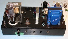
I've recycled the experimental chasis from my Spud amp project and drilled a few more holes, filled a few more shapes and as Sakuma-san would say 'mounted the iron'.
That's about it for now, next steps will include wiring up some bits and pieces, probably start with the power supply development. I'll find out soon enough if I'm missing any parts !
Have fun,
Jeff Medwin
Then it's time to tinker. If I wait until I have all the bits and a clean chassis I'll be old and grey. Actually I am getting old and grey 😡
I've recycled the experimental chasis from my Spud amp project and drilled a few more holes, filled a few more shapes and as Sakuma-san would say 'mounted the iron'.
That's about it for now, next steps will include wiring up some bits and pieces, probably start with the power supply development. I'll find out soon enough if I'm missing any parts !
Attachments
Member
Joined 2009
Paid Member
Terrible, I should be expelled. I have some serious family and work items that are very demanding, some of them not so good actually.
Anyhow, the hobby space needed a clean up, which is mostly done. I will not bother with the experimental chassis now, but commit to a proper build on a new and fresh chassis. So I will get a new Hammond box on order.
Anyhow, the hobby space needed a clean up, which is mostly done. I will not bother with the experimental chassis now, but commit to a proper build on a new and fresh chassis. So I will get a new Hammond box on order.
^that is okey Bigun, i myself has seven tube amps in various stages of completion....
at least three are fully built but i have not mustered enough courage to power it up....😉
powering up for the first time scared the hell out of me....
at least three are fully built but i have not mustered enough courage to power it up....😉
powering up for the first time scared the hell out of me....
Member
Joined 2009
Paid Member
I didn't forget about this project but it will morph a little into something similar I suspect. Definitely more ugly.
Member
Joined 2009
Paid Member
Don Garber Fi 2A3
Time to rekindle my interest in this project.
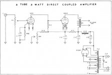
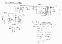
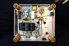
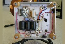
I read a little while back that Don Garber has passed on. He left a legacy of a very well regarded 2A3 mono-block amplifier. For me, it epitomizes the goal of this project, a nice little valve amplifier. I decided to take a peek at what he made. Attached are my findings. You will see that the topology is essentially that of the Robin & Chapman circuit published in a book in 1947 called 'Practical Amplifier Diagrams' and has 45 circuits inside. It sold for $2, or about $6 in todays money. The circuit of interest appears on page 6 as a "3 Tube 3 Watt Direct Coupled Amplifier". No doubt Shishido and Asano took inspiration from this design too.
Clearly, in the case of the Fi, the driver tube is operating at low current (e.g. 0.4mA) and the 2A3 likewise idling lower than 'standard' at around 40mA. These operating points are similar to the Serious Stereo too.
I could do worse than clone the Fi design for my project.
Time to rekindle my interest in this project.
I read a little while back that Don Garber has passed on. He left a legacy of a very well regarded 2A3 mono-block amplifier. For me, it epitomizes the goal of this project, a nice little valve amplifier. I decided to take a peek at what he made. Attached are my findings. You will see that the topology is essentially that of the Robin & Chapman circuit published in a book in 1947 called 'Practical Amplifier Diagrams' and has 45 circuits inside. It sold for $2, or about $6 in todays money. The circuit of interest appears on page 6 as a "3 Tube 3 Watt Direct Coupled Amplifier". No doubt Shishido and Asano took inspiration from this design too.
Clearly, in the case of the Fi, the driver tube is operating at low current (e.g. 0.4mA) and the 2A3 likewise idling lower than 'standard' at around 40mA. These operating points are similar to the Serious Stereo too.
I could do worse than clone the Fi design for my project.
Attachments


Last edited:
I have not gone through the previous 21 pages of this topic.
(I'm not sure if the fix is completely the same)
Here's some info from audioasylum,
Direct Coupled 6SF5-6B4G Amp Question - SomeJoe - Tube DIY Asylum
look for posts by Ejam
RE: Direct Coupled 6SF5-6B4G Amp Question - Ejam - Tube DIY Asylum
r5 is wrong, but he corrected in the following post.
RE: Direct Coupled 6SF5-6B4G Amp Question - Ejam - Tube DIY Asylum
this fix shows 2 chokes
Fi X Integrated 2A3 SET Amp (Magnequest trannies) and Y Preamp: Don Garber classic units xtra tubes Photo #1565080 - US Audio Mart
the fi x 46 version shows 2 chokes in the power supply
Don Garber's Magical Fi X4 Stereo Amplifier A stunning 1.5 watts with Tung-Sol 46 for only $1095! Review By A. Colin Flood
Your amp is looking good!
Last edited:
Member
Joined 2009
Paid Member
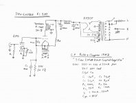
Thanks for those links - I've updated my schematic for the Fi 2A3 accordingly.Here's some info from audioasylum
my amp is back to square one. I'll be ordering a new chassis. I'd like to get it built before the winter is done, it's a 'winter amp'.Your amp is looking good!
Attachments
Member
Joined 2009
Paid Member
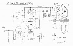
There are a couple of things I'd like to retain from my earlier doodles, rather than cloning the Fi 2A3 as is
a) independent control over the value of the driver plate load resistor which establishes gain and somewhat the harmonic profile
b) the hum reduction from the 'Westinghouse' ultrapath capacitor connection to the 2A3 cathode
c) a two-choke power supply filter, based on advice received about avoiding a large single choke large capacitor supply
My power transformer requires the use of a bridge rectifier to get the voltage I need so I'll use a hybrid bridge as being the closest option.
Attachments
I just went over the previous 21 pages of this topic-ugh.
Here's something simple,
Simpler SE 45/2A3 Amplifier
2A3 Stereo Amplifier on a Budget
EZINDEX
Some of my amps are on pages 808 & 809, If I were doing this amp I would either hardwire extra sockets to try other tubes or try socket adapters. But space considerations you might not want more sockets. My pp6v6 I use either 12ax7, 6sl7 or 5751- I can't tell any differences. Maybe it's the cct, I don't know. BTW my pp6v6 has only 2 caps in the amplifier cct. from 1951. My Preamp I plug in either 6sn7 or 6fq7 I don't have to look for a socket adapter.
another tube to consider - 6sq7, I've had this on the breadboard I like it. It's= 12ax7 1/2 note- it has diodes Dynaco Push-Pull EL84/6BQ5 or 6V6/6AQ5 Tube Amp Schematic
check half way down (some people will agree and some will disagree) amplifiers vacuum tube systems hi-fi hihighend 6c33c triode SET OTL's
Member
Joined 2009
Paid Member
I am using 1uf 16 volt ceramic caps for input coupling to the amplifier. This is to remove any residual DC at the input resulting from power on or bass control input offset. in or out of the circuit ( shorted ) I can't tell any difference at all. I would use a "better" capacitor if it made any difference at all.
On the 6922 preamp a .22 / 250 mylar sounds excellent.
would biasing the grid at -55 volts and .1uf / 400v blocking caps allow the use of a single heater transformer and a lower B+ of 250 to 275 volts ?
The quality of the Bypass Capacitor will be more profound as it is in the primary current amplification path
Last edited:
Member
Joined 2009
Paid Member
I've had very good experience with NP0/COG ceramic caps in my SS amplifiers, where I use them everywhere I can. For signal input I've also had good results with - yes - an electrolytic, specifically the Nichicon MUSE Bipolar type.
For this amplifier, I want to use the dc coupled approach. I've no experience with 2A3 amps and have no scientific reason to avoid a coupling cap other than the risk of blocking distortion on -Ve peaks of the input signal. But I like the idea and I like the positive reviews I've read of several different incarnations of 2A3 amps that are direct coupled. In all cases they are cathode biased, not fixed (grid biassed), all for good reasons.
It's a 'winter amp', with lots of heat wasted in the cathode resistor, the use of inefficient tube rectifier too.
Member
Joined 2009
Paid Member


- Home
- Amplifiers
- Tubes / Valves
- A nice little valve amplifier