Hey thanks for the info. I been wanting to delve into a 2A3 amp myself. Also have been studying the low dcr ps aspect. I recently converted my KT88SE to lowish dcr and I like it.
drlowmu,
Just curious, does the 2A3 amp in question happen to be based on the Shishido 2A3 with a modified low dcr power supply?
Thanks,
Scott
That design is better than most, if one didn't know better, has aspects of what to do, but it can not be copied directly and needs to be improved upon. Other have improved it, Dennis Fraker for one. Dennis HELPED Nobu design the Inverted Transformer Coupled amp BTW, they were audio buddies back then.
The Shishido 2A3 amp starts off wrong, you can NEVER ever parallel two sections of a high mu sensitive 12AX7 in this amp, and NOT get skewing of the sound, resulting in a lack of clarity, improper diction, improper enunciation.
And of course, the entire Shishido power supply needs to be thrown away, and begs to be replaced with a LSES or Low Storage Effect Supply, sometimes what I refer as a "modern" power supply.
Scott, low DCR is only part of such a supply filter to the 2A3 Finals, it must also be low in HY, under 2.5 HY, and low as possible in "C", 50 uF maximum typically. Well wired too !!! The whole amp design counts, can't segregate any one aspect !! You have mail Scott.
Jeff Medwin
Thanks for the reply Jeff. Yes, I've read what I was able to find available (mostly by you) about the LSES model. I used a CLCLC for my KT88SE. Much improved. The only weakish link in that supply is the PT which could be lower DCR.
Watching this thread with interest. Looking forward to building my 2A3SE.
Watching this thread with interest. Looking forward to building my 2A3SE.
Thanks for the reply Jeff. Yes, I've read what I was able to find available (mostly by you) about the LSES model. I used a CLCLC for my KT88SE. Much improved. The only weakish link in that supply is the PT which could be lower DCR.
Watching this thread with interest. Looking forward to building my 2A3SE.
Scott,
I like all supply iron to be under 20 Ohms DCR. However, it is the chokes, and not the power transformer, that are most critical in the finals to the filters. It has been proven to me by Dennis Fraker's Serious Stereo 2A3 amps, which has a high DCR power transformer, yet it playes with great speed and dynamics, and a fabulous low end, using below 10 Ohms DCR chokes as in L1/C1/L2/C2 to the finals.
Would it be better if the power trannie were lower in DCR, perhaps, but My Goodness, no one touches it now, or comes close, as it sits ( or he builds it ) in 2014 !!
Jeff Medwin
Member
Joined 2009
Paid Member
Some judicious proding from Jeff - I’ve dusted off the parts I had bought for this amplifier. It looks like I have the tubes and all the iron in hand.
I need a chassis - something a bit ‘traditional’, like Sun Audio (see post 87 too). A Hammond 12” x 8” - but Aluminium or Steel ?
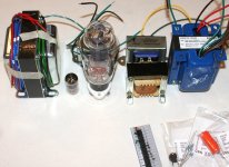
And what about the layout of parts - do it like the photo ?
Left to right: OPT - tubes - heater trafo / PSU chokes - power trafo. This keeps the OPT away from the rest of the iron.
I need a chassis - something a bit ‘traditional’, like Sun Audio (see post 87 too). A Hammond 12” x 8” - but Aluminium or Steel ?
And what about the layout of parts - do it like the photo ?
Left to right: OPT - tubes - heater trafo / PSU chokes - power trafo. This keeps the OPT away from the rest of the iron.
Attachments
Last edited:
Member
Joined 2009
Paid Member
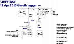
I don't think that October drawing will be the final schematic, but it is very close. I have learned that the RC filter for the input tube is unnecessary with this Loftin-White topology, which would simplify things further.
However, this L-W approach also raises the output impedance of the input tube which is a concern because when this impedance is combined with the input capacitance of the output tube you get a reduction in output at high frequencies (although at my age this is unlikely to be relevant !)
Before I tackle that question I'm going to start off by building the power supply and making sure I have a safe source of 500V and that means some chassis work and other stuff - as you can see, this ain't my fastest project !
To drive a 15 inch speaker I would go push pull maybe 10 watts.
Not sure you need those chokes in the power supply, I would just use resistors.
I designed a 80 watt push pull amplifier and didn't use any chokes and it sounded fine so for a few watts you should be OK.
Not sure you need those chokes in the power supply, I would just use resistors.
I designed a 80 watt push pull amplifier and didn't use any chokes and it sounded fine so for a few watts you should be OK.
Member
Joined 2009
Paid Member
I have been interested in a tube PP just because it would be new for me. I have a suitable power trafo somewhere and some Pentodes. Mind you, the 15" speaker didn't sound too bad using a 6AS7 SE amp so the 2A3 might not be an issue. If not, heck, I'll have an excuse to build another speaker!
I like chokes, I even use them on SS amps.
I like chokes, I even use them on SS amps.
Member
Joined 2009
Paid Member
I took a bash at converting the spice simulation Goldenbear posted in another thread to match the circuit that Drlowmu had suggested to me. I'm not sure that I've followed his instructions correctly. The results are distortion of 3% at 1W output. I'm not sure I'm happy with that, I'm pretty sure Jeff gets 1% at most from his amplifiers. Perhaps the tube models aren't accurate enough.
Attachments
That model doesn't seem very practical. With 42mA and a 5.6k cathode resistor, the cathode is at 23V, with 185V on the grid. He must mean 56K at the cathode. That's about 10 Watts over that resistor.
Sheldon
Sheldon
in my 2A3 builds i used 250 volts plate and 60mA cathode current on a shuguang tube...
sounded very well indeed...
sounded very well indeed...
Member
Joined 2009
Paid Member
That model doesn't seem very practical. With 42mA and a 5.6k cathode resistor, the cathode is at 23V, with 185V on the grid. He must mean 56K at the cathode. That's about 10 Watts over that resistor.
Sheldon
56k with 43mA will drop 2.4kV... no, the 5k6 if fine and this is the 2A3 model that Goldenbear was using. I provided the 12AX7 model (from somewhere else on this forum).
it was a misread.....would like to try direct coupling sometime in near future...
don't forget to lift the heaters of the 12ax7....
don't forget to lift the heaters of the 12ax7....
Member
Joined 2009
Paid Member
no problem,
but - is the conclusion that the Spice sims are not going to give me real distortion predictions, just tell me if all the voltages and currents are in the right places ?
but - is the conclusion that the Spice sims are not going to give me real distortion predictions, just tell me if all the voltages and currents are in the right places ?
Bigun, how about running your sims on my operating points? 250v and 60mA...
i did a paralleled 5894 SET running on simmilar operting points and l liked it as well..
i did a paralleled 5894 SET running on simmilar operting points and l liked it as well..
Member
Joined 2009
Paid Member
Hi AJT, I have tried it and the distortion drops to 2% at 1W but I am trying to understand better the design choices taken by others before me.
Perhaps you can help again here. Attached is the 2A3 attributed to Isamu Asano, a well regarded design.
Question: like the design Jeff proposed to me, Isamu uses an RC filter to drop the B+ significantly for the front end. This means using a low current through the input tube and a load resistor of 330k. With a less aggressive 'R' in the RC filter (less than the 60k he used) there could have been a larger load resistor for the input triode, or a higher current through the input triode. WHY did Isamu choose this operating point for the input tube - was he looking for some 2nd order cancellation between the two triodes ??
Attachments
i'm not that knowledgeable, but i think the goal there was first to bias the output tube by selection of input plate voltage...
and as expected bias of the output tube was 245 volts and 60mA....just as i did with mine...
dc coupling brings a lot to the table imho by getting rid of the coupling caps...
and as some would have it, the best coupling cap, is no coupling cap...😉
btw, a red led in the cathode of the input tube gives another dimension...
Hi AJT, I have tried it and the distortion drops to 2% at 1W but I am trying to understand better the design choices taken by others before me.
WHY did Isamu choose this operating point for the input tube - was he looking for some 2nd order cancellation between the two triodes ??
This is a pretty typical Loftin White type amplifier design, with the added disadvantage that there's no hum pot. (So you get to buy 2A3's till you find a pair that happen to be quiet on the filament windings you've been dealt!)
My guess is that the design is very old, and that the priorities were to have adequate gain in a 2 stage amp and a self adjusting grid bias voltage. What is sacrificed with this design is bandwidth (a limitation of the driver working against the Miller capacitance of the 2A3), hum nulling pots for the filaments, output power, and very likely noise floor (power supply issues).
To get the gain with the available tubes, you end up with a high mu triode with high plate resistance. To load this tube properly, you really need that 330K resistor, and to load the tube with the available voltage, and with some adjustment based on 2A3 current draw, you just can't run any more current than that.
- Home
- Amplifiers
- Tubes / Valves
- A nice little valve amplifier