the two Shuguang 2A3's i built did not have any hum issues from get go,
i installed humdinger pot in one. while i used the center tap in the other....
i merely set the humdinger pot at center span, and when i powered up the amp,
i found that i did not have to touch at at all....
agree on the bandwidth, trading bandwidth for phase shifts
caused by the coupling caps is a good trade-off imho...
in my 5894 SET i used a cathode follower to take care of miller,
and an aikido style front end using the 12at7...
the two Shuguang 2A3's i built did not have any
agree on the bandwidth, trading bandwidth for phase shifts
caused by the coupling caps is a good trade-off imho...
No, it's a stupid tradeoff. There are MANY other tubes that could be used with slightly less gain that would not have the bandwidth issue.
Also, your speakers are going to create waaayyy more phase shift than a single coupling cap will.
another way perhaps is to parallel sections to double transconductance and lower plate resistance in half and thus increasing gains...
You'll end up confounding the issue. Will what you hear be related to the issues that come with paralleling triodes? Or with the lowered source impedance? Etc.
It's a worthwhile experiment to do, but I'd add it to the other 2.
It's a worthwhile experiment to do, but I'd add it to the other 2.
there is a tube that has twice the transconductance of a 12ax7....can't recall now...
or a trioded D3a will make a better choice....
or a trioded D3a will make a better choice....
Member
Joined 2009
Paid Member
The thing is, with the 2A6 tube he had the internal resistance was 91k and even then he was running it at half the current the 2A6 was designed for so the internal resistance might be a bit higher. That means he has a loading factor of 330k/91k = 3.6 which is rather low. Darius recommends 4 or higher, Hugh Dean recommends 5 as do many other folk.
I can see why each of the components have the values chosen except for the Rp. But did he need a -60dB ripple filter for the input tube ? If less would have been OK then he could have increased Rp by another 30k or more for a loading factor of over 4.
I agree about the Miller thing, but many people have built directly coupled 2A3 amps with wimpy driver tubes and found them very much to their liking. The 12AT7 has a spec. better suited to this design but the plate curves don't look as good as the 12AX7 ? There are boundless options including triode wired pentodes like the E180F or 6E5P but these are high gm and a whole different thing. There is something special about a simple high mu triode that people have found very desirable in this topology.
Member
Joined 2009
Paid Member
And here we have the Nobukazu Shishido 2A3 with a very similar topology. Once again we see the operating point for the input tube. Yes the two halves are paralleled, but each tube is at only 0.5mA, similar to Asano. And the ratio of Rp/Ra is 150k/40k = 3.7.
Both Are very similar so perhaps the Shishido design was simply based on Asano with a modern input tube instead of the 2A6.
Again, there is a pair of resistors designed to drop the B+ voltage to the front end. Whereas Asano used a 60k + 50k divider Shishido uses lower values of 25k and 22k which has the benefit of flowing more current. A larger cap is used (100uF vs 20uF) to ensure the RC filter is still as effective.
the designers have decided that the effective B+ for the front end should be only 295V - 300V to achieve a particular operating point.
Attachments

Last edited:

yes, having a fairly large plate voltage for the input tube is a plus...
considering that the 2A3 grid is biased at -45 volts, having 150 volts at the 12ax7 plates
means there is a lot more swing available to push the 2A3 grids around..
i suppose you can run 12ax7 with more plate current though but i am not sure what it will bring....
considering that the 2A3 grid is biased at -45 volts, having 150 volts at the 12ax7 plates
means there is a lot more swing available to push the 2A3 grids around..
i suppose you can run 12ax7 with more plate current though but i am not sure what it will bring....
Member
Joined 2009
Paid Member
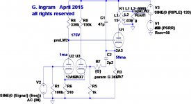
Looking at a Loftin-White noise cancelling option
The 12AX7 doesn't do well without a bypassed Rk, gain falls, plate impedance rises and h.f. roll-off starts way too early.
One option is to reduce Rk so that the plate impedance is kept reasonable. I think this can be achieved if the other half of the 12AX7 is used as a buffer to driver the hum cancelling signal into the cathode of the input tube. I alluded to this approach earlier in the thread.
The attached schematic explains the idea. Simulations show that it preserves the gain and drive capability of the input triode. It avoids use of a Ck and achieves the L-W noise cancellation. It also retains the same triode loading factor as Isamu and Shishido with Rp/Ra about 3.7
Attachments
Last edited:
The 12AX7 doesn't do well without a bypassed Rk, gain falls, plate impedance rises and h.f. roll-off starts way too early.
One option is to reduce Rk so that the plate impedance is kept reasonable. I think this can be achieved if the other half of the 12AX7 is used as a buffer to driver the hum cancelling signal into the cathode of the input tube. I alluded to this approach earlier in the thread.
The attached schematic explains the idea. Simulations show that it preserves the gain and drive capability of the input triode. It avoids use of a Ck and achieves the L-W noise cancellation. It also retains the same triode loading factor as Isamu and Shishido with Rp/Ra about 3.7
You cite this :
"The 12AX7 doesn't do well without a bypassed Rk, gain falls, plate impedance rises and h.f. roll-off starts way too early."
That is correct. Yawn. So, instead of trying to eliminate the bypassed Rk, why not spend some time and money thinking of how to execute it properly, and as best as possible ??
A properly executed Rk bypass takes lotsa $$$ to do well, as only the best quality caps will work well, but it brings something to the table that you can't get any other way !!
What does it bring ?? The ability to linearize the circuit by ear, at the speaker voice coil. How?? Different value caps tend to play different parts of the music, and, by combining the Rk Bypass caps artistically, we can gain more in music's nuances, layering, and subtle clues, that make listening more realistic to our ears, and to our minds and emotions.
I think there are only one or two people in tube audio world who have optimized the art of Rk bypassing. Its time others self-taught themselves how to do so.
With an ideally bypassed Rk, one half of a 12AX7, running under 1 mA. becomes the best possible tube candidate to run the 2A3 grid in a direct coupled two stage amp. How is that for a statement, conventional dudes ?? !!!
Of course, average tube enthusiast people look to conventional theory, so.... NO ONE can figure out how it gets done. The Serious Stereo DC 2A3 amp made in Montana by Dennis Fraker exists ( since 1989 ) and fulfills ALL the criteria, and is living proof of what I espouse. Think some, about HOW to best bypass an Rk, and we on our way !!
Member
Joined 2009
Paid Member
... linearize the circuit by ear, at the speaker voice coil. How?? Different value caps tend to play different parts of the music, and, by combining the Rk Bypass caps artistically, we can gain more in music's nuances, layering, and subtle clues, that make listening more realistic to our ears, and to our minds and emotions.
I do believe people hear a difference when they use different capacitors so there is some benefit from optimizing them by ear. However, to optimize it for my ears on my voice coil sounds expensive although the 'journey' would no doubt be educational. And will the result still be valid when my ears are 5 years older, or when I change to a different speaker, or use a different room, or for my sisters ears ? - I'm skeptical this is the right approach unless I want something very specific. I want to hear what a dc coupled 2A3 can do well, for a reasonable level of outlay and effort.
Last edited:
Stop with the sales-pitch already, YAWN...😀Of course, average tube enthusiast people look to conventional theory, so.... NO ONE can figure out how it gets done. The Serious Stereo DC 2A3 amp made in Montana by Dennis Fraker exists ( since 1989 ) and fulfills ALL the criteria, and is living proof of what I espouse. Think some, about HOW to best bypass an Rk, and we on our way !!
I do believe people hear a difference when they use different capacitors so there is some benefit from optimizing them by ear. However, to optimize it for my ears on my voice coil sounds expensive although the 'journey' would no doubt be educational. And will the result still be valid when my ears are 5 years older, or when I change to a different speaker, or use a different room, or for my sisters ears ? - I'm skeptical this is the right approach unless I want something very specific. I want to hear what a dc coupled 2A3 can do well, for a reasonable level of outlay and effort.
Bigun,
It IS expensive, and that, and a lack of knowing WHAT to do, is why only a few people KNOW to do bypassing properly.
When you are 70 or 80 yyears old, and can't hear over 5 KHZ, you will know how to bypass properly. The resultants come down into the midrange, where you DO and CAN hear, and you will tell ( and enjoy) hearing it right !!!
Pretty cool, eh !!
Jeff Medwin
Stop with the sales-pitch already, YAWN...😀
Thats not meant as a sales pitch. its just the facts as I know them.
Dennis is the only Manufacturer in SE audio I am aware of, who has done bypassing optimally, every cap in the circuit !!! Most either are clueless, or, are too cheap to spend the money, and time, to do it right.
Since only the best caps will do, it is easy to spend more money on bypass caps, than all other parts of the build. Its nice to know someone is aware and willing to be doing it well.
RE: Hopefully, Mr Fraker will join us, as you suggested.... - tube wrangler - Tube DIY Asylum
Have fun,
Jeff Medwin
 You've been warned before about your promotional efforts. Desist or confine them to the commercial areas.
Member
Joined 2009
Paid Member
Crickey! - what a thread that is, sock puppets, personal attacks and whatnot. Thank goodness we don't put up with that stuff here - DIY Audio rules 😎
Back to business - this thread is about a nice little valve amplifier.
If I press forward with the parts on hand I will end up with a SS rectifier and this is going to result in a current surge through the 2A3 when it's filament comes up to boil and has to charge up it's associated cathode capacitor. Before running back to tube rectifiers I want to give some thought about an elegant solution to this.
Last edited:
Crickey! - what a thread that is, sock puppets, personal attacks and whatnot. Thank goodness we don't put up with that stuff here - DIY Audio rules 😎
Back to business - this thread is about a nice little valve amplifier.
If I press forward with the parts on hand I will end up with a SS rectifier and this is going to result in a current surge through the 2A3 when it's filament comes up to boil and has to charge up it's associated cathode capacitor. Before running back to tube rectifiers I want to give some thought about an elegant solution to this.
Double ON OFF switching with Filaments having Priority, and, about a 10 uF main film cap, PLUS its critically chosen multiple film bypasses for the 2A3 Rk. Not the single large uF capacitor you show. With one film Rk cap, the music will "tune" to its value - which should be avoided.
Jeff Medwin
Attachments

Last edited:
i favor separate plate and filament power traffos, i am making a set of traffos for
a Tabor clone that my friend is building...it will have just two traffos, two OPT's and two chokes....
delayed B+ is good for transmitting tubes running B+ in the kV range..
for home use amps, who cares? not me....
a Tabor clone that my friend is building...it will have just two traffos, two OPT's and two chokes....
delayed B+ is good for transmitting tubes running B+ in the kV range..
for home use amps, who cares? not me....
- Home
- Amplifiers
- Tubes / Valves
- A nice little valve amplifier