Back then, limiting only happened at fairly strong signals because more IF stages = extra cost + difficulty to remain stable (>100 dB gain at 10.7 MHz, not trivial). But in sets with a ratio discriminator, that already provides AM rejection (contrary to Foster-Seeley) so the user only notices a lower audio level. Adding an amp boosting the antenna signal might improve the situation - grounded grid tube amp (planar triode) can provide NF below 2 dB at 100 MHz.Interesting project, I am working on a clairtone console using ecc85 for the front end and 6BA6 for 2 IF stages. Works well except for limiter function output goes up and down with signal strength.
Thanks you boys. I'm planning to make my FI trafos also tuned with copper slugs. I'm collecting data from IRE proceedings and magazines from worldradiohistory. Valuable info found.
Sorry, my mistake, I thought I saw 'AFC' in there. Must have been dreaming.I don't understand that remark. Ideally the limiter output signal should depend on the phase but not the amplitude of the limiter input signal, shouldn't it?
The limiter maintains the FM signal at a fixed level before the demodulator. The tube receiver's audio output varies with RF signal strength.
Such an effect would require an extra circuit including a variable gain stage (audio). No circuit diagram available?The limiter maintains the FM signal at a fixed level before the demodulator. The tube receiver's audio output varies with RF signal strength.
No it wouldn't. A ratio detector already does limiting, and so does grid-leak limiting into a sharp cutoff valve run at a low plate voltage. Audio has nothing to do with it, this is IF.Such an effect would require an extra circuit including a variable gain stage (audio). No circuit diagram available?
Last edited:
Solid-state FM radios sometimes have a very hard limiter and a softmute circuit that attenuates the audio a bit when the reception is very weak, or when you tuned to interstation noise. Otherwise the interstation noise is too loud to most people's taste. Another way to reduce interstation noise is to design the limiter such that it doesn't limit at very low levels, I think that is the more common method in valve radios (requires less valves).
As an aside, the local radio station here used to have a portable 223.25 MHz FM transmitter used by reporters. The receiver had a very hard limiter and no softmute. There was a compressor built into the transmitter and an expander in the receiver. You got quite a scare from the sudden very loud noise when the reporter unexpectedly switched off the transmitter.
As an aside, the local radio station here used to have a portable 223.25 MHz FM transmitter used by reporters. The receiver had a very hard limiter and no softmute. There was a compressor built into the transmitter and an expander in the receiver. You got quite a scare from the sudden very loud noise when the reporter unexpectedly switched off the transmitter.
Edit: This is a late answer to #58 and #60:
As I also don't have a curve tracer, I've accustomed myself to mark unknown and identical looking tubes inmidst the pin circle with a sharpie, i. e. »3« for EF183, »4« for EF184, »0« for EF80, »5« for EF85 etc. This also applies for tubes with different heating (»E«, »P«, »U«). Of course this needs to be done when the designation still is visible or right after pulling the tube from scrapped gear when you know it's position, hence know what it is.
Best regards!
Not really. It clips off the AM noise so that a constant IF level is presented to the demodulator, because most if not all demodulators will demodulate AM as well as FM, and you only want to demodulate FM.The limiter maintains the FM signal at a fixed level before the demodulator.
No it doesn't. Audio amplitude is encoded as frequency deviation. Audio output therefore varies according to the deviation from the carrier frequency.The tube receiver's audio output varies with RF signal strength.
Your two statements are mutually contradictory. The demodulator can't know anything about the RF level after the limiter.
No it isn't. He was talking about audio limiting, which does not occur in an FM tuner.
I interpret post #65 as a statement that if the limiter keeps the IF level at the demodulator constant, the audio can only depend on the RF level when there is some auxiliary circuit changing the audio level depending on the RF level. That's correct, it is precisely what we do with softmute circuits. Softmute would be unusual in a valve radio, though.
All in all, I think you, I and Aridace basically agree.

On the SDR I haven't seen any FM signal carrying SCA here (regards transmissions from Colombia, Costa Rica, Panama. Even RDS is sparsely used (wouldn't justify a hardware decoder).Thanks to all for the good dialog here.
Is there still SCA tranmisions elsewhere in the world?.
Your interpretation is correct, and part of my past job was to present unusual issues. The easy DIY solution with semiconductors was a BPF in the gap between audio and the lower 38k sideband but avoiding the stereo pilot signal. Should be easy with valves as well but as you mentioned, would be unusual.I interpret post #65 as a statement that if the limiter keeps the IF level at the demodulator constant, the audio can only depend on the RF level when there is some auxiliary circuit changing the audio level depending on the RF level. That's correct, it is precisely what we do with softmute circuits. Softmute would be unusual in a valve radio, though.
All in all, I think you, I and Aridace basically agree.
Ultrasonic noise detection to control the softmute. That is more elegant than the received-signal-strength-based approach, because it keeps working properly when there is more atmospheric or human-made noise than expected.
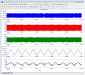
The FM noise spectrum indicates that processing noise works better and faster at the highest possible spectral part of the demodulator. Absence of SCA and RDS makes the job easier. Noise-controlled mute / squelch is indispensable when using a PLL demodulator.Ultrasonic noise detection to control the softmute. That is more elegant than the received-signal-strength-based approach, because it keeps working properly when there is more atmospheric or human-made noise than expected.
Why a PLL demodulator? Threshold extension, trying to reduce the required IF filtering, something else?
This list might help, at least when they are Philips valves: https://frank.pocnet.net/other/Philips/PhilipsCodeListAB-v10.pdfI've several EF183's & EF184's but the white painted label is erased. Anyone know anybgood form to distinguish between them? I haven't curve tracer.
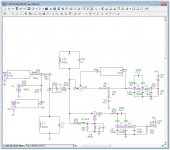
The lower threshold of a PLL improves reception noticeably (noise, capture ratio) so worthwhile for fringe areas and DX reception. Fairly easy to model (pics added) so can be optimized.Why a PLL demodulator? Threshold extension, trying to reduce the required IF filtering, something else?
Attachments
- Home
- Source & Line
- Analogue Source
- A new FM tuner with Compactron Tubes