SY said:Is it any crazier than the great Birdcage amp at ETF07? 😀
exactly ..... that's my kind of F4 , not that sissy Variac's one ........

Yeah, I've got a similar attitude- if an amp can't kill you when you're careless, it's not worth working on.

agent.5 said:1000V+ amp for the next burning amp festival?
maybe Papa will bring 1000A amp .........

edit:
and I'll bring toob preamp for it ...........
The NOT Mute LED.
Argh!!! - why did'nt any of us pick that up earlier. Oh well - change it to a Green LED and call it an Operate LED and the design and PCB are perfect!!! You could even run it to the front panel.
Changing the requirements specification (after the event) to suit what you accidentally built is a very well recognised and widely used engineering practice.
Cheers,
Ian
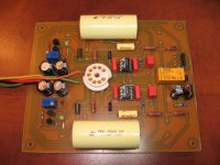
I would like to complete the preamp and listen to it, but I've being on the road for work a lot since the last month, and PCB assembly and basic testing is the only thing I can do in an hotel room.
Since this circuit is using HV, I also would like to complete the external power supply enclosure and have it nice a tidy, so nothing get shorts out.
Still working also part time on the Pumpkin preamp. This complex circuit took me a long time to get all the needed parts and assemble it.
I was really interested to test the PCB's to be sure there was no error on them. My projects take me a long time to complete. I've being also busy building PCBs for other diyers, so there was not much left for my own work. And there was the Montreal Hi-Fi Show weekend, etc...
But I'll get there eventually...
By the way my best sound at the show was from a superb Leben integrated tube amplifier driving a pair of ProAc speakers. Just gorgeous.
Too bad the Leben was over 5K
Thanks for that Algar-emi. Makes hooking it up a lot easier.
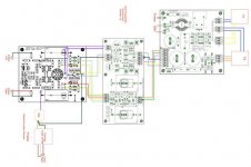
A question: See where you have 120V in (X1-L; X1-N) - this is the mains supply in correct? I take it that its routed through the PCB and then onto the transformers for the high and low tension supplies?
Apart from getting the correct secondary on T1 and T2 is there any changes to the BOM for using this with 240V?
Nice work on the diagram- certainly makes it easier. This is the most complicated pre I've built yet so all the help is great to have.
Have you listened to yours yet? How do you like it?
Fran
woodturner-fran, just plug the 240V to X1. In the BOM, insure that the MOV protection RV1 chosen at the input accept 240V. The specify value is good up to 275V. It may be a little too short for 240V. Also change the fuse value, cut its Amp value in half if use under 240V instead of 120V. I using for the moment 1A, so use 0.5A as a starting point. I think also that in Europe, it is a good practice to use a double poles power switch and kill both line voltage sides.
You need the correct primary, not the correct secondary 😉
The chosen transformers Triad VPS230-110 (HV) and VPS36 (LV) accept both 120 and 230-240V primaries, just connect them correctly (in parallel for 120V, in serie for 240V). So, you can still use the same part number.
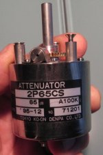
Sorry, not completed yet. I need time to assemble the external supply first, then make the preamp enclosure. I'm a little afraid to use HV equipment without proper grounded enclosure. And I was looking for the good volume control. Just got the nice TDK step attenuator.
I may also build inside a phono section using Allan Wright Phono Stage design (just one tube per channel, see schematic). I'll use HV shunt regs PCB that I was planning to use since a few years. Hence, my enclosure design may change to accept the phono section.
You need the correct primary, not the correct secondary 😉
The chosen transformers Triad VPS230-110 (HV) and VPS36 (LV) accept both 120 and 230-240V primaries, just connect them correctly (in parallel for 120V, in serie for 240V). So, you can still use the same part number.
Sorry, not completed yet. I need time to assemble the external supply first, then make the preamp enclosure. I'm a little afraid to use HV equipment without proper grounded enclosure. And I was looking for the good volume control. Just got the nice TDK step attenuator.
I may also build inside a phono section using Allan Wright Phono Stage design (just one tube per channel, see schematic). I'll use HV shunt regs PCB that I was planning to use since a few years. Hence, my enclosure design may change to accept the phono section.
Attachments

Sy,
As we discussed the Heretical in another thread I began simming something similar. Couldn´t the input cap be eliminated by using the transformer and pot for biasing? The ouput from the opamp should then be looked upon as a "virtual" earth. The pot should, inspite of the DC, also be noisefree as the potential is the same on all terminals. Yes, I know, the second 6DJ8 is no ideal CCS. Just thought of making the signalpath C and sandfree😉 !
As we discussed the Heretical in another thread I began simming something similar. Couldn´t the input cap be eliminated by using the transformer and pot for biasing? The ouput from the opamp should then be looked upon as a "virtual" earth. The pot should, inspite of the DC, also be noisefree as the potential is the same on all terminals. Yes, I know, the second 6DJ8 is no ideal CCS. Just thought of making the signalpath C and sandfree😉 !
Attachments
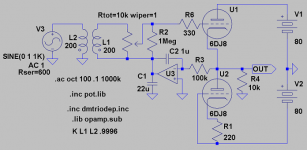
That will work, but now the servo's output is directly in series with the input. In my version, you do need the input coupling cap (but a small one!), however the servo's output is divided down by the 10M in series with the Thevenin equivalent of the 10k resistor in parallel with the source impedance.
In theory, you could substitute a tube CCS for the bipolar one, but effectively, the cathode load is the driven load anyway because the CCS impedance is so high. If you went that route, I'd use a pentode.
In theory, you could substitute a tube CCS for the bipolar one, but effectively, the cathode load is the driven load anyway because the CCS impedance is so high. If you went that route, I'd use a pentode.
plate supply as servo ...?!
What about taking a fixed negativ grid voltage, feed it into the cold end of the secondary and using the plate supply voltage as a servo? 😎
Kind regards,
Darius
What about taking a fixed negativ grid voltage, feed it into the cold end of the secondary and using the plate supply voltage as a servo? 😎
Kind regards,
Darius
- Status
- Not open for further replies.
- Home
- Amplifiers
- Tubes / Valves
- A Heretical Unity Gain Line Stage part III