Already been done. The F4 topology can scale up as big as you want, if you have the heatsink. Look at the BA-3 amplifier. BA-3 balanced would get you that kind of current and swing in a very straightforward manner.
I'm on the BA-3 based preamp path right now... with tape monitor, balance, headphone amp and hopefully balanced pre-outs. I suppose I could add a transformer for the voltage gain...
How big would a 200 wpc F4 (or BA-3 current gain) set up be? My A2s are on the 5U, deep deLuxe chassis. I don't want to go larger than that. And, remember I'm looking for 200 wpc into 4 ohms.
I want to split the preamp and amp(s) for many of my own reasons.
I guess I'll have to delay my retirement until I get these beasts built.
Just found out I should have read the thread before ordering parts. Can't develop enough bias with the 10k Ohm resistors for R9. Can I use 3.3k Ohm (closest on hand to 4.7k)? Can someone give me a hint to how to figure this out? I'm assuming Ohm's law applies here somewhere.
@6sX7 : Sounds like you need to increase R8 or decrease R9. See post #2931: https://www.diyaudio.com/community/...ass-f4-amplifier.234355/page-147#post-7018397
Since it seems you are already getting some bias current (ie. the mosfets are already turning on), you don't want to change things too much that the new min voltage is too high to get the bias you want.
Since it seems you are already getting some bias current (ie. the mosfets are already turning on), you don't want to change things too much that the new min voltage is too high to get the bias you want.
Last edited:
..........
Honestly, the day Nelson Pass designs the F4 Turbo V4 he might as well retire from amps and endeavor himself to preamps, transformers and high efficiency speakers!
........
he did that already, numerous times
just take a look in any of regular/bigger PL amps


Getting 200mV on the right channel, 170mV on the left.How close can you get? What other resistors do you have? Anything between 10K and 4.7k?
The simple solution, ha! Last night at 9pm, didn't seem so obvious.Or, couldn’t you piggyback a 10k onto r9…
That's the info I'm looking for, trying to get deeper into understanding circuits. Thanks Dennis! Time to go break out the coffee, calculator and cogitation.@6sX7 : Sounds like you need to increase R8 or decrease R9. See post #2931: https://www.diyaudio.com/community/...ass-f4-amplifier.234355/page-147#post-7018397
Since it seems you are already getting some bias current (ie. the mosfets are already turning on), you don't want to change things too much that the new min voltage is too high to get the bias you want.
Temporary solution following myleftear's suggestion. Piggybacked a 10k resistor via alligator clips. Getting 170mV across the source resistor with the bias pots dialed all the way down. Guessing 3.3k will be too little. Ordered some 4.7k as recommended. Still working thru what the circuit does mathematically. I did verify that I've got 2.493V between the reference and anode of regulator (Q11). Brain hurts. I think my physics brain died when I became a manager. Bloody neck tie cutting off the circulation.
Attachments
he did that already, numerous times
just take a look in any of regular/bigger PL amps
OK.... but all of those amps have the voltage amplification front end built in, right? Only the F4 has no voltage amplification. So, pretty much it becomes a "preamplifier follower"... it changes my component paradigm, you see. Up until now, the preamp would stay constant while the amps rotated... now it becomes a "constant amp" with "rotating preamps" affair. An interesting proposition.
Besides, and realizing that you guys have to make a living... those PL amps are really pricey. I'd love to have a pair of XA200.8s.... but they are physically imposing, very expensive (got to pay for the fine looks) and I would need a new living room to fit them in.
I do have to say I love that XA25 amp... I tried to buy a used one from a dealer in TX. Offered a reasonable, honest price. He refused. Six months later he finally sold it for hundreds less than I offered him. As much as I love power, I'm finding out that the lower powered amps sound better. I suppose it's reasonable to expect that less parts, all other things being equal, will sound better.
Oh well, I'm having a great time listening to the F4.. and now I suppose I will need yet another pair of amps. Thanks Nelson - and you too. ;-)
Last edited:
SissySiT. On plan. Besides, I've read your stuff.... pretty funny. ;-)
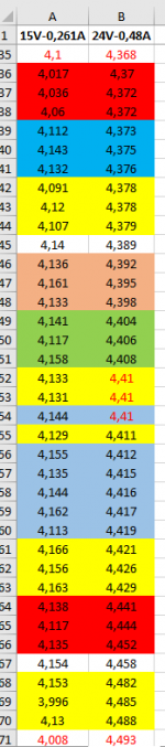
Are those triplets god for F4, matched at 15V and .25A for 30 seconds, and after 2 days matched again at 24V and 0,48A for 30 seconds? Matching is done on a very large heatsink. I think is better to choose the higher voltage because is closer to the real operation point, am I right? Thanks.
Attachments
I got one monsterblock up and running. Replaced R9 with 6.19k Ohm and having no issue with bias range. Set the biasing voltage to 200mV and let the amp sit for an hour. I could leave my hand on the heatsinks indefinitely. Then, per 6L6's experiments, ramped it up to 300mV. No idea what the distortion profile looks like as I don't have the instrumentation. It is stable at 300mV with very little offset in each channel, somewhere around 1mV (limit of the Fluke DMM). The heatsinks are quite warm, warmer than running the F6 boards but I can make it to 10 seconds before thinking it might be a good time to take my hand off of them.
Put the amp in the system as a stereo amp using the RCA inputs. The Benchmark DAC3 will get the Halcyons loud but not drive you out of the room loud. Adjusted the balanced output jumpers for no attenuation and hooked the amp up as a balanced monoblock. Running a single balanced amp, the one Halcyon got loud enough to satisfy my gain curiosity. Once I get the other channel up and running, the system should be able to drive me out of the room.
No critical listening but a quick hear of the 1st track of Adele's 21 had me thinking there is a naturalness and presence to her voice that I didn't hear with the F6s. The mind is a trickable beast so who knows what I'm hearing. Thinking if there is some way to make a meaningful comparison but planning to get the other amp converted on Monday. Hoping to report back then on how the stereo sounds with F4 monsterblocks.
Got 3 out of 4 channels of the monsterblocks working correctly. Getting odd bias behaviour from the right channel of amp 2 (call it RchA2). All other channels start out with a biasing voltage of ~170mV. RchA2 starts out at about half, ~85mV. When I get RchA2 biased up to 300mV, the heatsink is 10C more than the other channels. Hooked it up to the system and have some very clear distortion going on. Any quick ideas? Pictures to come in the next day or so. Have to tear the chassis apart to get clear close-ups and a bit burnt after a marathon DIY day yesterday.
…it’s 4 screws to pop the lid off and get some photos. Let us take a look, lots of eyes can see things you cant.
Alright, alright. You talked me into it. Bad angle due to tight quarters, the offending channel:


Got 3 out of 4 channels of the monsterblocks working correctly. Getting odd bias behaviour from the right channel of amp 2 (call it RchA2). All other channels start out with a biasing voltage of ~170mV. RchA2 starts out at about half, ~85mV. When I get RchA2 biased up to 300mV, the heatsink is 10C more than the other channels. Hooked it up to the system and have some very clear distortion going on. Any quick ideas? Pictures to come in the next day or so. Have to tear the chassis apart to get clear close-ups and a bit burnt after a marathon DIY day yesterday.
output DC offset, for functional channels , and for non functional one?
clarify " the heatsink is 10C more than the other channels"
output DC offset of all channels can be trimmed down to limits of the MM, 1mV.output DC offset, for functional channels , and for non functional one?
clarify " the heatsink is 10C more than the other channels"
Heatsink for RchA2 sits at ~56C. Heatsink for all other channels, ~47C
Last edited:
if source resistors are the same, Iq is set to same value ( voltage sag across source resistors), rails are the same ...... physics sez that heat W are the same ...... and hsink temp must be the same
if htsnk temp is not same, you need to find what else is not the same, to decipher root reason for unequal temperature
check voltage sag across each source resistor, in all channels, to be sure that each and every current path is functional
easy as that
if htsnk temp is not same, you need to find what else is not the same, to decipher root reason for unequal temperature
check voltage sag across each source resistor, in all channels, to be sure that each and every current path is functional
easy as that
- Home
- Amplifiers
- Pass Labs
- A guide to building the Pass F4 amplifier