Ben,
To answer your first question, my previous voltages for R6 & R7 were relative to ground.
Today I measured the PSU as 22.18 and -22.10 V
And R6 @ 21.03 and R7 @ -20.53 relative to ground.
I'm getting ready to build a fresh left channel, as I'm not too keen to remove the JFets again and I've gone over all my solder joints.
Maybe a mystery is just a mystery.
I really appreciate the help you've provided along the way.
One question, 6L6 in post 112 says: "There is no place where you need a matched pair of J74 in that circuit... " so I can use new JFets in a new left circuit board without need to match to right channel, correct?
To clarify, what I meant was “F4 does not use matched pairs of J74, it uses matched K170/J74 pairs.”
So in order to use the J74 you have you’ll need to buy a whole bunch of K170 to find mates, or just buy a fresh set of matched K170/J74.
So in order to use the J74 you have you’ll need to buy a whole bunch of K170 to find mates, or just buy a fresh set of matched K170/J74.
I sourced from the DIY store as always.
I think I will swap out the JFets with new ones and try the left channel again.
I think I will swap out the JFets with new ones and try the left channel again.
Strange… unless you made some kinda mistake and blew them (since they worked in the beginning though the chan had lower volume)… would be interesting to know if their IDSS is above the bias level. Since you say they actually measure correctly off circuit. But of course, there may be other more reasonable explantations.
Sounds like a route worth trying. Good luck, and kudos for the stamina! A great amp, though I only have the OS in my BA-3 🙂
Sounds like a route worth trying. Good luck, and kudos for the stamina! A great amp, though I only have the OS in my BA-3 🙂
Thanks for the observation. I'm using JFets from the store. P-ch Idss is 6.90mA and the N-ch Idss is 6.04mA
Last edited:
The new ones will have these values:
P-ch Idss = 6.78mA
N-ch Idss = 6.68mA
Better match, though I don't think that is/was the core issue.
More will be revealed.
P-ch Idss = 6.78mA
N-ch Idss = 6.68mA
Better match, though I don't think that is/was the core issue.
More will be revealed.
Sounds fine, but matched worse than advertised…
I wouldn't necessarily conclude that given the Peak atlas measures at
low and non-constant Vds voltages:
https://www.diyaudio.com/forums/pas...ilding-pass-f4-amplifier-272.html#post6722091
The Idss values quoted in the spec sheets for these parts are at Vds=10V.
I installed new JFets. Biased up to .17 V
Had readings on all Mosfets.
Regarding the three resistors that I had no readings for yesterday, here are the new values - all V
R1 0.0 V
R3 -0.097 V
R4 -16.35
PSU value 22.30 V / -22.40 V
R6 to G is 17.01 V
R7 to G is -16.23 V
Clearly R1 is a problem and R3 looks very low.
Bad resistor at R1? Nope reads correctly.
Hmmm, something is stilled screwed up.
Appreciate any thoughts.
Are the R1, R3 and R4 readings the voltages across those resistors? If so then
R1 is OK since there should be no current flowing through it.
R3 seems a bit low.
R4 doesn't make sense at all; please verify the R4 value and the unit of measurement.
R1 is OK since there should be no current flowing through it.
R3 seems a bit low.
R4 doesn't make sense at all; please verify the R4 value and the unit of measurement.
Assuming your voltages for R1, R3, and R4 are across the resistors:
If the voltage at R1 is across the resistor, zero voltage is good, indicating no DC in the input.
If -16.35V is across R4, it doesn't make any sense.
If -0.097V is across R3, it looks ok - indicates -0.097V/22.1R=0.0044A through the resistor and the SK170.
Please be very clear what your measurements represent.
Please measure again:
- Voltages across R3, R4, R6, and R7.
- Voltages with respect to Ground at both ends of R3, R4, R6, and R7.
Better to have more information so that measurements can be verified.
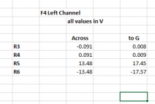
I assume it's R6 and R7, not R5 and R6. If so, the numbers look acceptable. I did ask for voltages at both ends of the resistors with respect to Ground just as a further check.
At the JFET source resistors R3 and R4, the 0.091V drop across gives 0.091V/22.1R=0041A = 4.1mA, a bit low compared to 5mA expected but it is in the ballpark. Perhaps the JFETs have lower Idss.
But it looks like the channel is working.
At the JFET source resistors R3 and R4, the 0.091V drop across gives 0.091V/22.1R=0041A = 4.1mA, a bit low compared to 5mA expected but it is in the ballpark. Perhaps the JFETs have lower Idss.
But it looks like the channel is working.
Oops...you have better eyes than I do. 🙂
I think Chiptech mentioned his jfets have 6-ish mA Idss.
@Chiptech: Can you confirm you have low DC offset?
I think Chiptech mentioned his jfets have 6-ish mA Idss.
@Chiptech: Can you confirm you have low DC offset?
Yea, the JFETs he has now should be above 6. but Chip where those numbers given by the seller or measured by you? As Dennis pointed out your method might not be 100% accurate for this purpose. Given the IDSS is that low, I would consider asking for a reimbursement. You might not be able to tell the difference between 4 and 5 mA, but it means they don’t bias to spec, and if the IDSS is too low, you won’t be able to manipulate it up through resistor changes either. But as you pointed out the fets prolly aren’t the main cause of all of this.
Still excited to see what the solution to your issues turns out to be! Or is it all working now?
Still excited to see what the solution to your issues turns out to be! Or is it all working now?
Last edited:
I assume it's R6 and R7, not R5 and R6. If so, the numbers look acceptable. I did ask for voltages at both ends of the resistors with respect to Ground just as a further check.
At the JFET source resistors R3 and R4, the 0.091V drop across gives 0.091V/22.1R=0041A = 4.1mA, a bit low compared to 5mA expected but it is in the ballpark. Perhaps the JFETs have lower Idss.
But it looks like the channel is working.
I meant R6 and R7.
My Jfets are from diystore. they are the Jfets in the 6-8mA range. Should I be using the 8-11 mA instead?
- Home
- Amplifiers
- Pass Labs
- A guide to building the Pass F4 amplifier