you'll see numbers on DVM creeping up, then slowing ....... then almost stopping
measure a dozen or so , without writing values down , just for experience and getting feel sake
then measure for real
don't skimp on heatsinking and pressure
I'm using forced cooling , just to keep temp as steady as I can ....... in case that I do it more often than it\s already the case , I would invest my time in obtaining temp controlled plate instead of heatsink
anyway, it's close enough with simplest methods
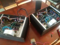
Hi all. Just finished building my second f4 and have a question about paralleling the outputs...
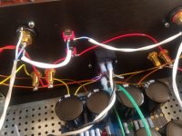
As you can see below, I put in switches so I could link the inputs and outputs to switch from stereo to mono. The input switches are working like I anticipated, bridging the RCA's so that whatever I've got on one channel comes out both.
The output switch is not, however. In the manual, Nelson says you have to connect the red speaker outputs when paralleling. Flipping that switch, however actually kills any output on the cross channel, even if the RCA's are bridged with the top switch.
If I just use an external wire then everything seems to work as expected. Any thoughts would be appreciated.
Thanks for all the help, the stereo is sounding better than ever.
Attachments
pull that garbage switch out and do it correctly , with piece of wire between terminals
switch is small and prone to melting if soldered by someone with less than 1K hours of soldering experience ...... so good for line level signals only
though , by pictures ...... Gremlins are in action , if there is no signal out if you engage that output switch
btw. invest some time in sorting that wiring - shorter, thinner, fatter and neater ..... if nothing else- matter of principle
Last edited:
I actually had the switch action reversed, so it actually was working. I kept turning it off. Stupid.
For outputs maybe use 10A rated mains wall light switch designed for reliably passing high current. They have large screw terminals so crimp and solder beefy forked terminals onto 16ga or larger wire. Put a 1uF film cap across contacts to absorb that spark.
no need for that switch, wire bridge between terminals is proper way to do it
besides - what's happening with 1uF when he doesn't need parallel operation ?

besides - what's happening with 1uF when he doesn't need parallel operation ?
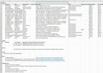
Now that both F4s are singing, I thought I'd post my corrected parts lists... As before, happy to send the excel document if anyone wants it.
Thanks again everyone. I love this site/community.
May I ask why you used Carbon Film 10K for R6 and R7? Is it because R6 and R7 directly in signal path?
One more thing, I noticed you used RN60 for metal film. Do all of them fit well on the PCB? RN60 is quite long and fat. Thanks.
~Kecap
I'm being offered matched pair of:
2SK170V/2SJ74V; V= 10-20 mA (really 11-17 mA)
2SK170BL/2SJ74BL; BL= 6-12 mA (really 6.8-11 mA)
2SK170GR/2SJ74GR; GR= 2.5-6.5 mA (really 3-6 mA)
I'd appreciate some help to pick which is best option to go with. Thanks.
~Kecap
2SK170V/2SJ74V; V= 10-20 mA (really 11-17 mA)
2SK170BL/2SJ74BL; BL= 6-12 mA (really 6.8-11 mA)
2SK170GR/2SJ74GR; GR= 2.5-6.5 mA (really 3-6 mA)
I'd appreciate some help to pick which is best option to go with. Thanks.
~Kecap
BL are usual with Papa's conctructions
Well noted ZenMod. BL is way to go then. Thanks.
~Kecap
Hi, I am about to build a crippled f4. I have all parts in right value at hand except the zener diode. I have the 9.1V (1N4739) but not the 6.8V (1N4736) as specified in the BOM. Will it work to use 9.1V instead?
Thanks in advance
Thanks in advance
if you're thinking of D1 and D2 , ref. to schm in post #1, use whatever you have in range of 6V2 to 10V
they're here to protect mosfets of excessive Ugs
they're here to protect mosfets of excessive Ugs
May I ask why you used Carbon Film 10K for R6 and R7? Is it because R6 and R7 directly in signal path?
One more thing, I noticed you used RN60 for metal film. Do all of them fit well on the PCB? RN60 is quite long and fat. Thanks.
~Kecap
The cheaper carbon films were used for LED resistors. I think I chose them because I copied someone else's purchase. If I were to reorder, I'd just buy extra RN60s and use them there. As for the choice of RN60, I chose them because I had trouble finding RN55s and wanted Dale/Vishay resistors... just got forced into that size by mouser/digikey.
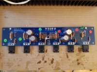
Here's a look at what a populated board is like. Everything there is RN60.
Attachments
The cheaper carbon films were used for LED resistors. I think I chose them because I copied someone else's purchase. If I were to reorder, I'd just buy extra RN60s and use them there. As for the choice of RN60, I chose them because I had trouble finding RN55s and wanted Dale/Vishay resistors... just got forced into that size by mouser/digikey.
Here's a look at what a populated board is like. Everything there is RN60.
I see, I made a wrong assumption then. It's a hassle to stock CF just for those LED. Thanks for the picture. Those RN60 looks like little sausage squeezed together.
~Kecap
- Home
- Amplifiers
- Pass Labs
- A guide to building the Pass F4 amplifier