From memory i left mine at 225 or 250 to keep the heatsink around 50-55c. The bias level and DC offset adjustment vary with temperature so i recommend you setup the amp where its going to live, then after an hour or so remove the top cover and tweak both adjustments again.
Enjoy!
Enjoy!
It's the 4u jack off all chassis I'm using. I think measuring it wheres it's living is a good idea.
One thing I did notice is that all the resistors measured slightly differently. I got matched mosfets from hannes but didn't buy shed loads of resistors to individually test. Does this matter. I think they're all within about 6mv of each other
One thing I did notice is that all the resistors measured slightly differently. I got matched mosfets from hannes but didn't buy shed loads of resistors to individually test. Does this matter. I think they're all within about 6mv of each other
Hi
A little question about thermal pads : i got aavid thermalloy aluminium oxide thermal pads, Much less expensive than keratherm. Should I add a drop of thermal grease - i have Silicon thermal grease - on both sides ?
Thanks
Jean-louis
A little question about thermal pads : i got aavid thermalloy aluminium oxide thermal pads, Much less expensive than keratherm. Should I add a drop of thermal grease - i have Silicon thermal grease - on both sides ?
Thanks
Jean-louis
Last edited:
Not sure. I didn't but I had mostly keratherm. I was a couple short so used some cheaper ones. One thing I did do was after i clamped te gets in place I checked that none of them had got punctured. I think it's the middle pin that connects to the metal plate on the back so made sure that wasn't conducting to the heatsink
Hi
A little question about thermal pads : i got aavid thermalloy aluminium oxide thermal pads, Much less expensive than keratherm. Should I add a drop of thermal grease - i have Silicon thermal grease - on both sides ?
Thanks
Jean-louis
I believe it's recommended.
All the hard interface materials MUST have some form of THERMAL compound to exclude the air from the interface. NO EXCEPTIONSHi
A little question about thermal pads : i got aavid thermalloy aluminium oxide thermal pads, Much less expensive than keratherm. Should I add a drop of thermal grease - i have Silicon thermal grease - on both sides ?
Thanks
Jean-louis
Only the soft thermal pads can be used without compound.
Thanks all, what was wondering me is that is was not written in the build guide, and I thought maybe with Keratherm it was not required.
All the best
All the best
As I'm getting the finishing bits n' bobs for my ACA amps (PE finally got new stock!) I am also trying to make a BOM for an F4 based on the likelihood I'll like the ACA's and on what I've read about the F4. I know it's a PITA and a lot to ask, but if anyone has a list already or could look over what I have and make suggestions I would greatly appreciate it. As most of you know it really bites to have to make 6 orders from Mouser because you keep missing one thing 🙂
Here's a link to what I have. I hope this works as I've never put an excel sheet online before.
https://onedrive.live.com/redir?resid=D14574D98CFBB21!112&authkey=!ACgK5Elk_sJqCaA&ithint=file,xls
Here's a link to what I have. I hope this works as I've never put an excel sheet online before.
https://onedrive.live.com/redir?resid=D14574D98CFBB21!112&authkey=!ACgK5Elk_sJqCaA&ithint=file,xls
Hi, I've recently built an f4 and also ordered from mouser. Unfortunately I can't open the link on my phone but....
You will need a matched set of mosfet output transistors which "hannes" can help you with.
Don't get them from mouser, they'll be all over the shop.
Obviously there's the jfets. I got mine from eBay and I think they're ok but if hannes has them get them from him.
You won't need the snubber resistors or snubber caps for the psu.
I struggled to find psu caps from mouser. But you may have better luck
You could use the big in-one bridges rather than mess about with diodes and heat sinks. The big bridge rectifiers I think bolt to the chassis. I would probably go that route rather than diodes and heat sinks if I were doing it again.
I would also get a couple of 27k and 33k resistors extra as the 22.1k resistor on the biasing (r8 or r9 I think, can't remember, you can raise one value or lower the other). I ended up just using a big standard metal film which I thinks ok but as I had put rn60 in the rest of it, it just kind of bugged me.
If you are using the soft start or speaker boards I would use spade connectors and not the clamp ones. The reason being particularly the soft start as it leaves mains voltage metal plates un insulated. I ended up wrapping electrical tape round to try and make it a bit safer.
If I think of anything else.....
BUMP
Hi all
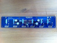
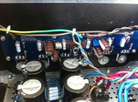
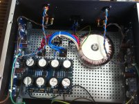
I finished my first F4, PSU is okay +24.6, - 24.6v, the leds are lit on the boards but there is no tension across the source resistors whatever is the trim pot P1 position. No smoke either. Same for Left and Right channels.
Visual inspection did not bring anthing.
I join a couple of pictures if it may help. What should I check first ?
Thanks a lot
Jean-Louis
Hi all
I finished my first F4, PSU is okay +24.6, - 24.6v, the leds are lit on the boards but there is no tension across the source resistors whatever is the trim pot P1 position. No smoke either. Same for Left and Right channels.
Visual inspection did not bring anthing.
I join a couple of pictures if it may help. What should I check first ?
Thanks a lot
Jean-Louis
Attachments
Last edited:
Argh Mighty ZenMod : got a 22R for R8 instead 22K, I screwed my BOM and my QC is poor obviously 🙂-(
Thanks for the ultra fast feedback ! Gotta order some more stuff now
All the best
Jean-Louis
Thanks for the ultra fast feedback ! Gotta order some more stuff now
All the best
Jean-Louis
- Home
- Amplifiers
- Pass Labs
- A guide to building the Pass F4 amplifier