Is the the max you can get? I got a max of 0.060v with the 22.1k and increasing to 27k gave me plenty extra.
OK Dave thanks for the advice, I will give it a try while before switching my 3rd and 4th board in with hopefully good TL431.
How is p1 affecting the voltage across the source resistors? If it is changing by a decent amount, make sure you turn it down before putting the new resistor in or the bias could shoot up!
If it's not really changing at all then maybe it is the tl431.
As I wasnt sure which way turning p1 was going to affect the bias, I tested the board on my bench supply ramping up gradually and making measurements as I went and my bench supply also displays how much current the board is drawing. I do have a reasonably powerful bench supply so make sure each rail can handle at least 1.5 to 2 amp at 24v. The board shouldn't draw that much at 200mV bias but you don't want to damage anything!
Been having a look at the data sheet
http://www.ti.com/lit/ds/symlink/tl431.pdf
Haven't got to the bottom of how the tl431 works yet. Probably too much wine.......if anyone can put a simple expiation my way that would be fab.
However it does seem that it wants the reference voltage to be in a very fine range, around 2.5 volts. I suspect that putting the 22r resistor in has put the device spectacularly outside its operating range and probably has fried it.
I think that the sensible thing to do is replace the tl431s and test before you change the 22.1k resistors. Otherwise you could find you leave in too high a value and when you "fix" the circuit you may cause further damage. Try to get the circuit working as close to stock then tweak
Sorry for any conflicting/just plain wrong info I may have put your way.
Look at it as an adjustable Zener diode (parallel voltage regulator). It has internal voltage reference (2.5V) and amplifier which is controlled by 2 external resistors that set the tl431's operating voltage....Haven't got to the bottom of how the tl431 works yet. Probably too much wine.......if anyone can put a simple expiation my way that would be fab....
Also, google for "tl431 calculator"
Yes, when I set R8=22R, I guess Vref has been higher than the maximum value (2.55v) and internal components must have been destroyed
TL431 | Shunt Voltage Reference | Voltage Reference | Online datasheet
Interesting, you learn from mistakes and have a good opportunity to go through the TI datasheet. BTW I cannot find from the schematics the voltage the TL is supposed to regulate.
TL431 | Shunt Voltage Reference | Voltage Reference | Online datasheet
Interesting, you learn from mistakes and have a good opportunity to go through the TI datasheet. BTW I cannot find from the schematics the voltage the TL is supposed to regulate.
BTW I cannot find from the schematics the voltage the TL is supposed to regulate.
Is Fig 27 here what you are looking for?
TL431 | Shunt Voltage Reference | Voltage Reference | Online datasheet
Cheers,
Dennis
In the F4 amp TL431 should provide the Vgs for output HEXFETs which is about two times 4-4.5V i.e. 8-9V.
Ok then I replaced the TL with my only spare and with R8 = 23.5k I got 86 mV so changed R9 to 5.1 K I finally obtained the 130 mV. Thanks to all !
Jean-Louis
PS : Juma thanks for the explanation
Jean-Louis
PS : Juma thanks for the explanation
Juma, are the 2 1n4736 (6.8v zeners) there to protect the output devices (and when i think about it, maybe even the psu) and make sure that the gate voltage doesnt exceed that and thus causing far too much current to flow.
This also leads me on to another thought. This is supposedly a current follower with zero voltage gain, but that being the case i would expect the biasing on the gate to be plus 12v and -12v with the voltage for each side swinging from 1v to 23v and similarly -1v to -23v.
It seems that the high voltage input gets attenuated somewhere and then the power mosfets are adding the voltage gain back in? Is that right?
Another F4 on
Hi all
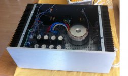
Thanks to Nelson for sharing the design and for all for your kind assistance, a new beast has waken up. Still a little bit of cleaning cables inside when back from vacations.
Just one word : impressing
- wide and precise stage
- very revealing but not fatiguing, really straight sound
- absolutely no noise on my high efficiency Tannoys with the ear 5 cm from the compression horn
- excellent bass control
I used R8=27 kO which gave me all headroom for the bias set at 200 mV hot. Vdc out is within 1 or 2 mV. Temperature is measured 50°C on the case radiators.
Re the building, I regret I did not use hex bolts for securing the mosfets and the PCB to the case, standards screw are quickly damaged when you screw - unscrew once or twice. I should have used the standard Diyaudio package as I could not find the right sizes at my Diy shop nearby. And I am very happy with the 4U case, I just made a amistake for the engraving, I thought it would come in blak on the silver but it did not, and I put it at a place where I would have put the handles, they would be quite usefull for moving the thing.🙄
Next steps will be
- going multiamp with a second one for medium plus a third low powered for treble (maybe with only one Mosfet ?)Should I change anything in the design except trafo VA ?
- adding 3 x BA3 front end, this is why I left some room in the case. I am using the Najda board as DAC, volume control, Digital XO, it can output 6v maximum which is enough for most of domestic listening but I would like from time to time to crank up a little bit the SPL.😀
Kind regards
Jean-Louis
Hi all
Thanks to Nelson for sharing the design and for all for your kind assistance, a new beast has waken up. Still a little bit of cleaning cables inside when back from vacations.
Just one word : impressing
- wide and precise stage
- very revealing but not fatiguing, really straight sound
- absolutely no noise on my high efficiency Tannoys with the ear 5 cm from the compression horn
- excellent bass control
I used R8=27 kO which gave me all headroom for the bias set at 200 mV hot. Vdc out is within 1 or 2 mV. Temperature is measured 50°C on the case radiators.
Re the building, I regret I did not use hex bolts for securing the mosfets and the PCB to the case, standards screw are quickly damaged when you screw - unscrew once or twice. I should have used the standard Diyaudio package as I could not find the right sizes at my Diy shop nearby. And I am very happy with the 4U case, I just made a amistake for the engraving, I thought it would come in blak on the silver but it did not, and I put it at a place where I would have put the handles, they would be quite usefull for moving the thing.🙄
Next steps will be
- going multiamp with a second one for medium plus a third low powered for treble (maybe with only one Mosfet ?)Should I change anything in the design except trafo VA ?
- adding 3 x BA3 front end, this is why I left some room in the case. I am using the Najda board as DAC, volume control, Digital XO, it can output 6v maximum which is enough for most of domestic listening but I would like from time to time to crank up a little bit the SPL.😀
Kind regards
Jean-Louis
Attachments
Please stay away from such thoughts. 😀...This also leads me on to another thought. ...
F4 is the source follower (input on gate, output on source) and since its output sits at 0V the gates are at about 4V (typical Vgs value for HEXFETs).
The rails being the 23V it means that the amp can only swing the difference between the Vgs and the rail voltage so 19V is the maximal peak voltage at the F4's output.
That's all there's to it...
Last edited:
The rest is cosmetic/auxiliary stuff that mrdave45 can live without going into details, but empty one-liners are going to help him a lot ...


I expect to be resuming my F4 builds soon. Four matching boards for driving a pair of 4 ohm speakers.
With the exception of the front panel power switch I think I have all of the parts based on the following transformer.
When I started the closest transformer I could find was a 20V 400VA from Antek. Now they have the 18V 400VA back in stock. I only purchased one at the time.
Should I buy a second 20V, or buy two 18V and try to sell the 20V? Both models are $65 for one delivered - $51 plus shipping.
Heat is a major issue, as in my air conditioner runs from March through December and the air handling unit doesn't make for the best listening environment. I don't know if the extra 2 VAC makes for significantly more to dissipate.
My garage is now climate controlled with a 1.5 ton Mitsubishi mini-split so my building environment will be an improvement and less clutter in the house to avoid annoying my wife.
I was in the same predicament when I ordered my last transformer from Antek, no 18V 400VA and I bought the 20V. I have another amplifier with a 18VA Antek. I personally do not think it is enough difference to worry about. I would probably go with another 20VA and not worry about it being such a small difference. Most all Firstwatt amps will work with higher voltages than 23V dc.
- Home
- Amplifiers
- Pass Labs
- A guide to building the Pass F4 amplifier