I have a few reasons:
1) Because I enjoy laying out a board as effectively as I'm able to. It's like a tiny puzzle!
2) If I go through my usual board fab company, I'll get three copies for a price similar (I think $10 more) to what I would be paying to get two of the diyAudio boards - letting me more easily add a center channel once I finish construction of that speaker.
3) It's one more facet of the construction that I get to do myself. I don't mind building kits, but if I ever feel like showing off my amps to classmates or colleagues, I'd like to be able to say "I designed that board layout."
Those are good enough reasons. 😎
Thought you were thinking of a more 'technical' reason. I myself are busy learning myself Altium/CircuitMaker, and the First Watt projects are prime candidates for first projects since they have so few components. A Crippled F4 with BA3 Front End on one board being one such project.
Last edited:
If there is an unsurmountable reason why I flat out can't do SMD components, I'm all ears, and then I'll just suck it up and buy the boards from the store.
If it's just the spacing on the MOSFETs and their cooling requirements though - I should be able to get them reasonably well spaced out, and I am not against adding active cooling in some capacity if it turns out I need to. The heating could also be an issue for the components themselves, but I am pretty confident that I have spec'd components that will be able to handle the environment.
Either way, I look forward to being able to construct these and give my speakers a better life. They can't be enjoying being fed by my old beat up receiver. 😛
There are none that I can think of. Which SMD part will you use to replace the 2SJ74/2SK170 with? I see Linear Systems has SMD packages for those, but what is odd is that they have the LSK170 in SOT23 package, whilst they have the LSJ74 in SOT89 package.
EDIT: It would have been nice if they had both these in the same package, such as the SOT89 package. It would be even better if they had both together in a single SOIC package.
EDIT: It would have been nice if they had both these in the same package, such as the SOT89 package. It would be even better if they had both together in a single SOIC package.
Last edited:
The transistors will stay as through-hole components. I think they can still be purchased in matched pairs in the TO-92 package, plus there's the need for thermally mating them. I don't pretend to know how to easily do that with SMT components.
The diodes I think I will also keep as through-hole, though that's mostly because I have a few of the zeners on hand already.
The diodes I think I will also keep as through-hole, though that's mostly because I have a few of the zeners on hand already.
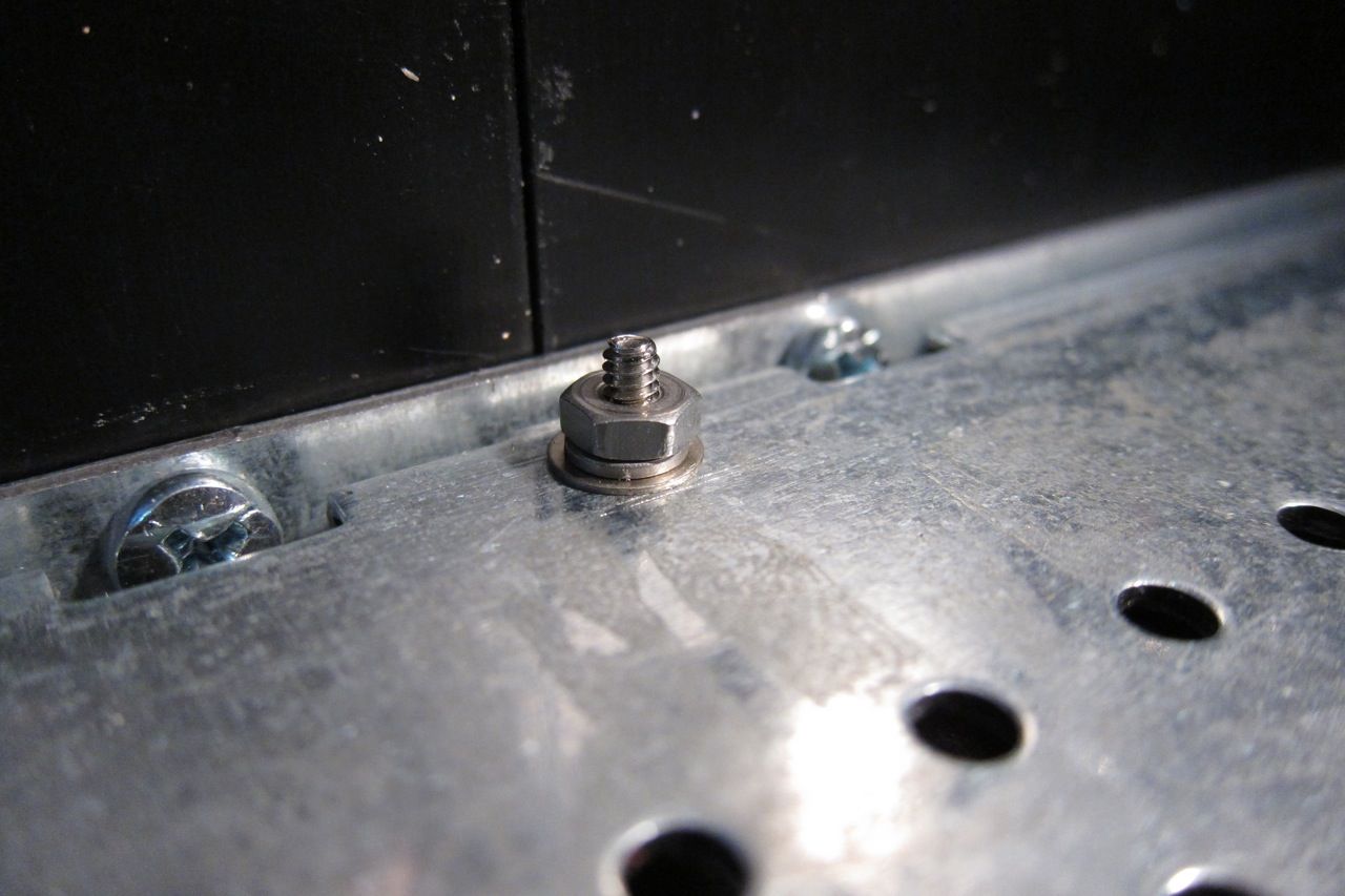
How far from the heatsinks should the PCB's be mounted - or what length of standoff?
I was hoping to get the boards mounted today but was sold standoffs which are too short. (from the bolt company, he said they were 1/4" but they are 1/8"). I tried to put a washer behind it to add a little height but only two threads will engage into the top of the standoff.
I was hoping to get the boards mounted today but was sold standoffs which are too short. (from the bolt company, he said they were 1/4" but they are 1/8"). I tried to put a washer behind it to add a little height but only two threads will engage into the top of the standoff.
It's the 2 threads of engagement which has me concerned, even with blue loc-tite. There is no "grip". Using #4 40 hardware for mounting which has an OD of 0.105, and that's about the same as the thread depth on the female end of the standoff at 0.10. With the first "row" of threads being tapered and not exactly engaging it comes to 3 threads at the most with only 2 doing any gripping. Additionally, I'm not going to have any screws short enough to mount the PCB without using a stack of washers so it's going to have to wait until next week.
Looking at the data sheet for:
8714 Keystone Electronics | Mouser
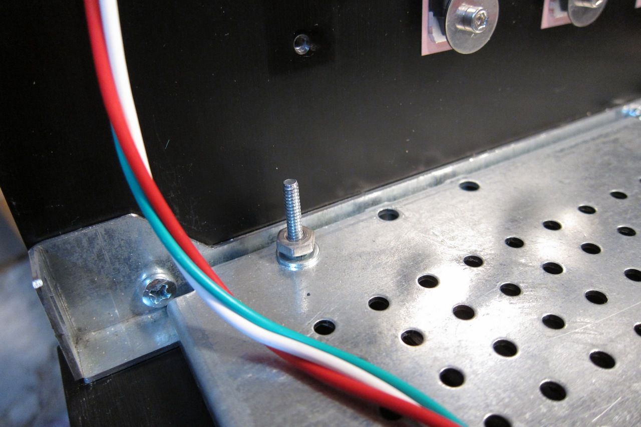
0.25" (6.35mm) standoffs, there is room for 0.13" (3.3mm) of internal thread in the standoff. I would prefer a little more thread engagement.
The next size up is 0.375" (9.53mm), it offers 0.25" of female thread depth. That's more than enough, but I'm at >0.4" (over 10mm?) to the top of the PCB.
If I had to guess based on photo's of builds, it's between the two sizes. Sensible metric, maybe 8mm?
I know the use of male / female standoffs is not required but it's a nicer build than using spacers. I see builds where 0.25" spacers are used and that may be what I end up using if I can't decide between the two sizes above. Easy enough to find... or simply cut them from scrap stainless tube on hand. The mounting of the PCB is not the only thing I have left to complete and do have time for another order from mouser...
Looking at the data sheet for:
8714 Keystone Electronics | Mouser
0.25" (6.35mm) standoffs, there is room for 0.13" (3.3mm) of internal thread in the standoff. I would prefer a little more thread engagement.
The next size up is 0.375" (9.53mm), it offers 0.25" of female thread depth. That's more than enough, but I'm at >0.4" (over 10mm?) to the top of the PCB.
If I had to guess based on photo's of builds, it's between the two sizes. Sensible metric, maybe 8mm?
I know the use of male / female standoffs is not required but it's a nicer build than using spacers. I see builds where 0.25" spacers are used and that may be what I end up using if I can't decide between the two sizes above. Easy enough to find... or simply cut them from scrap stainless tube on hand. The mounting of the PCB is not the only thing I have left to complete and do have time for another order from mouser...
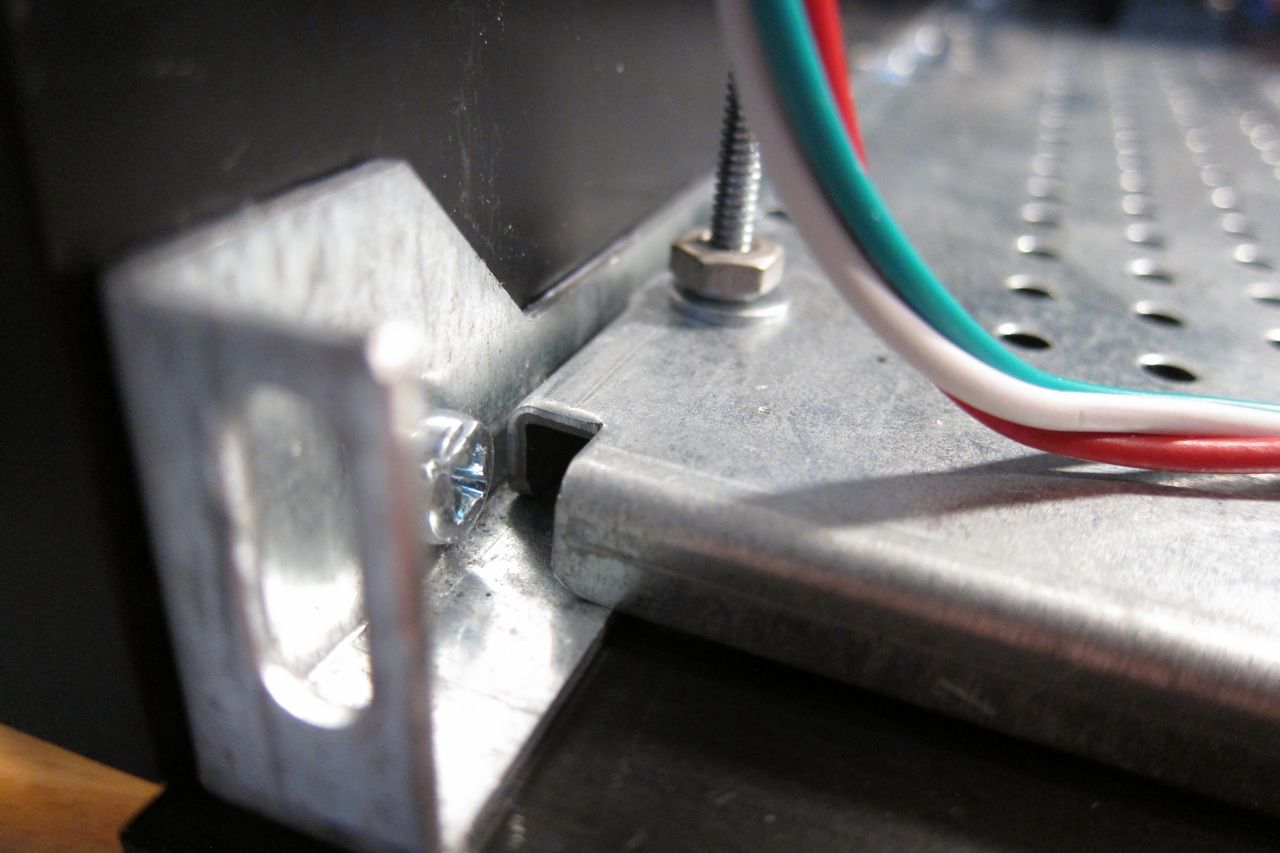
Mechanically the Mosfet need to be secure, and the PCB basically held in place.
As long as the PCB isn't going to shift around, it will be fine.
That said, more thread engagement than 2 thread's worth would be good.
As long as the PCB isn't going to shift around, it will be fine.
That said, more thread engagement than 2 thread's worth would be good.
I'm not sure if this matters, using the DIY Store F4 board layout:
I'm installing IRFP230/9240 "matched for this project" with small stickers put on the Mosfet's
240 have tags with labels of: 93, 110, 119
9240 labels of: 162, 163, 97
Looking that they both have one number that is farther from the other two does it make any sense to put them in a particular space. Right now I have the one farthest out of range at Q5 and Q10. I based the decision on not knowing exactly what the labels were and the original F4 diagram.
Not knowing what the figures will mean as far as temperature or other properties, assuming a 4U 300mm chassis (one piece heatsink)... better to have the low number in the middle between the other two, or putting them at positions closer to the center or outside of the heatsink where temperatures may be cooler? Maybe the low figure one's need to be warmer?
I still have 3 more channels to build and haven't looked to see what their deviation is.
Probably one more thing to not worry about but thought I would ask if there is a strong opinion.
Can you verify with the person who supplied your mosfets?
I know what I do is to first sequentially label all the transistors in a batch I
wish to measure, then measure them and select accordingly.
Cheers,
Dennis
I know what I do is to first sequentially label all the transistors in a batch I
wish to measure, then measure them and select accordingly.
Cheers,
Dennis
I'll probably misspell this but Alweit from Israel -apologies for misspelling. I think I ordered them in February asking him to match for 4 channels of F4
By all means verify with Alweit what was his matching/selection criteria, but knowing
that you got the parts from him gives me confidence the parts are good.
Don't mix up your sets though. There's no guarantee they match across sets. 🙂
Cheers,
Dennis
that you got the parts from him gives me confidence the parts are good.
Don't mix up your sets though. There's no guarantee they match across sets. 🙂
Cheers,
Dennis
I'm building a crippled F4 to use with a BA3FE.
I will build it with 32V rails. 50v caps will be used, but should I change any resistor values in the F4 schematic?
I will build it with 32V rails. 50v caps will be used, but should I change any resistor values in the F4 schematic?
Last edited:
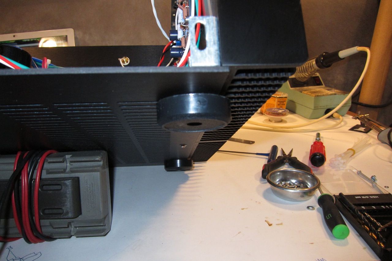
I just attached the first board to a heatsink and had a moment of clarity regarding the choice of capacitors and "easily" swapping them out for another.
The 18 pins of Mosfet, attempting to remove the solder, etc...
If it were your 16 capacitors (8 installed) of Nichicon Gold 50v, vs Elna Silmic (II?) at (35v, 50v?) it is obvious that this is the time to make the choice before soldering the Mosfet in place.
PSU is currently 35V Panasonic 15Kuf caps for 60Kuf per... or I picked up some 35V Chem-Con at 56Kuf for 112Kuf per if I make my own PSU board to fit the odd pinout. Transformer is Antek 4220 which I think is 20V, 400VA and mains are consistently at 125V which might bump the numbers up a bit.
Build plan is 2 mono blocks which I hope to run with a balanced preamp eventually but might turn into a chance to build an Aleph and sell one of the kits. That for reference only...
Just finish the darn build and be happy with it or buy the Elna caps? Never had an amp of this quality, but the thought of removing the Mosfet's...
Placeholder for 6l6
https://www.passdiy.com/project/preamplifiers/b1-buffer-preamp
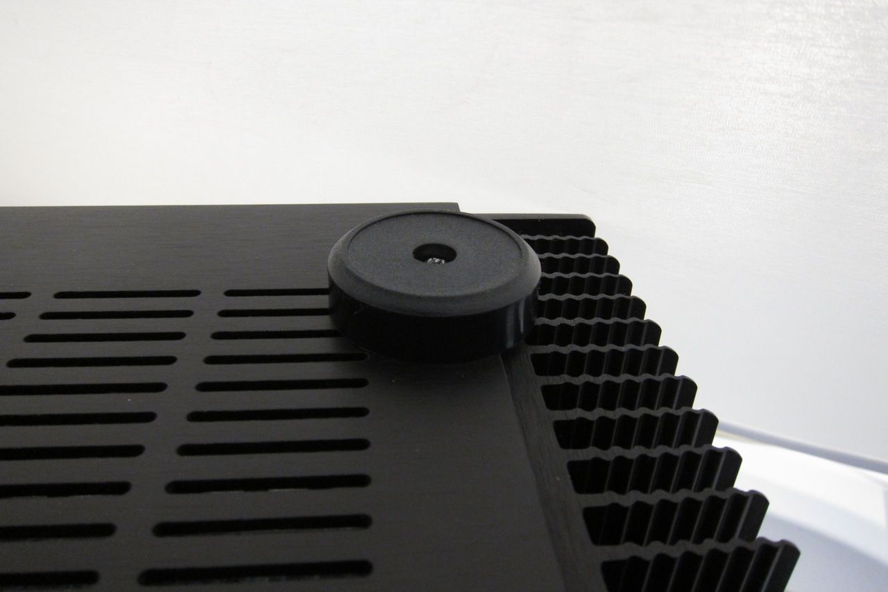
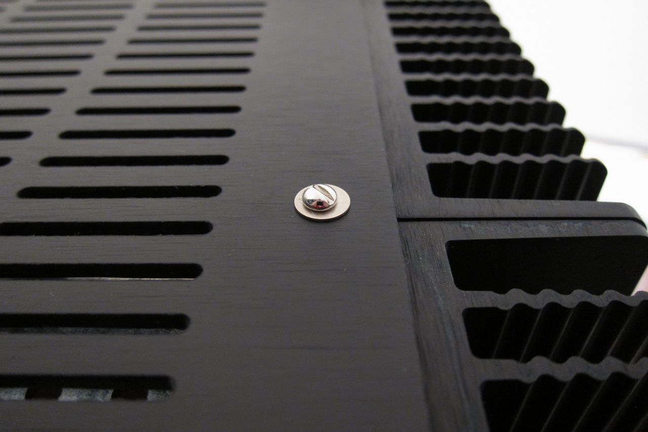
The eagle-eyed among you noticed that I had the perforated baseplate installed upside-down, so I needed to flip it over and mount it so the screwheads under the steel perf would not touch the actual baseplate.
The provided hardware is a bit short, so I needed to improvise - this is DIY, after all, so no big deal.
You can see here the perforated baseplate installed correctly.
When searching for screws, they always come in 2 lengths - too short and too long...
But those screws on the 4 corners do need to be longer than the center screws because the chassis feet are mounted with them.
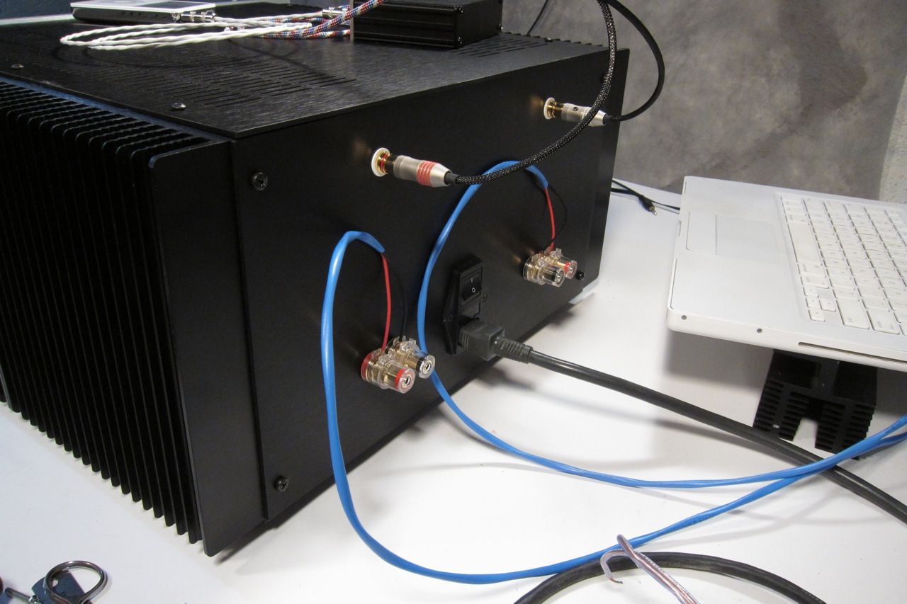
Amp bottom
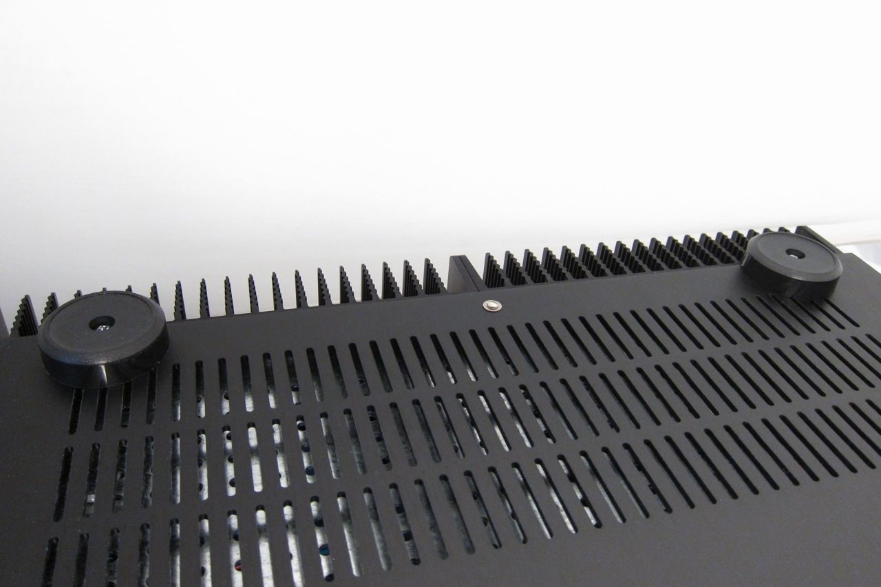
When complete, each side of the amp bottom should look like this.
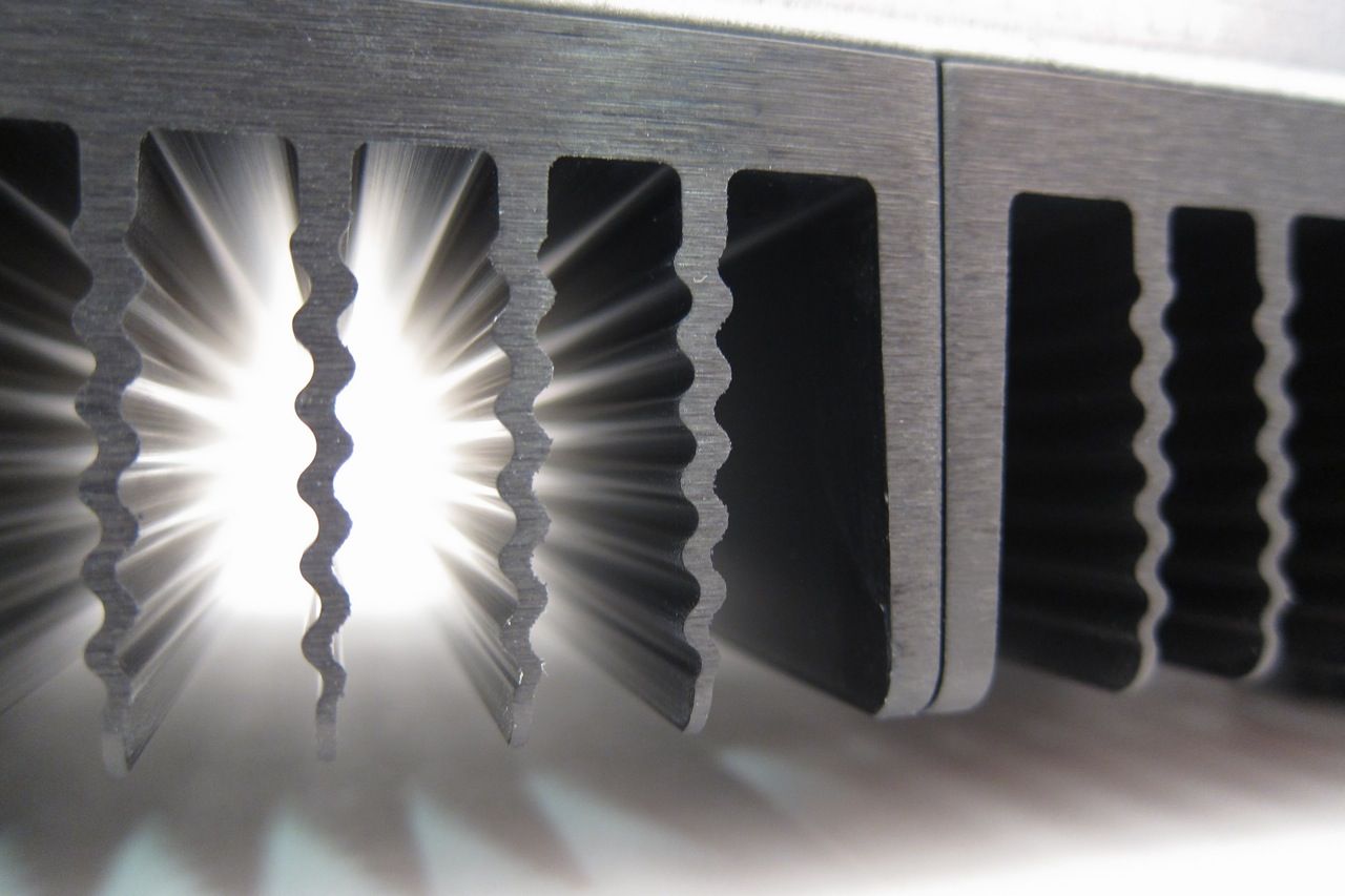
A neat photo highlighting the extrusion profile of the big heatsinks.
That completes it, the chassis is quite simple to assemble, and the pre-drilled back makes things really simple.
The amp goes together with very little effort -- it's a rewarding project.
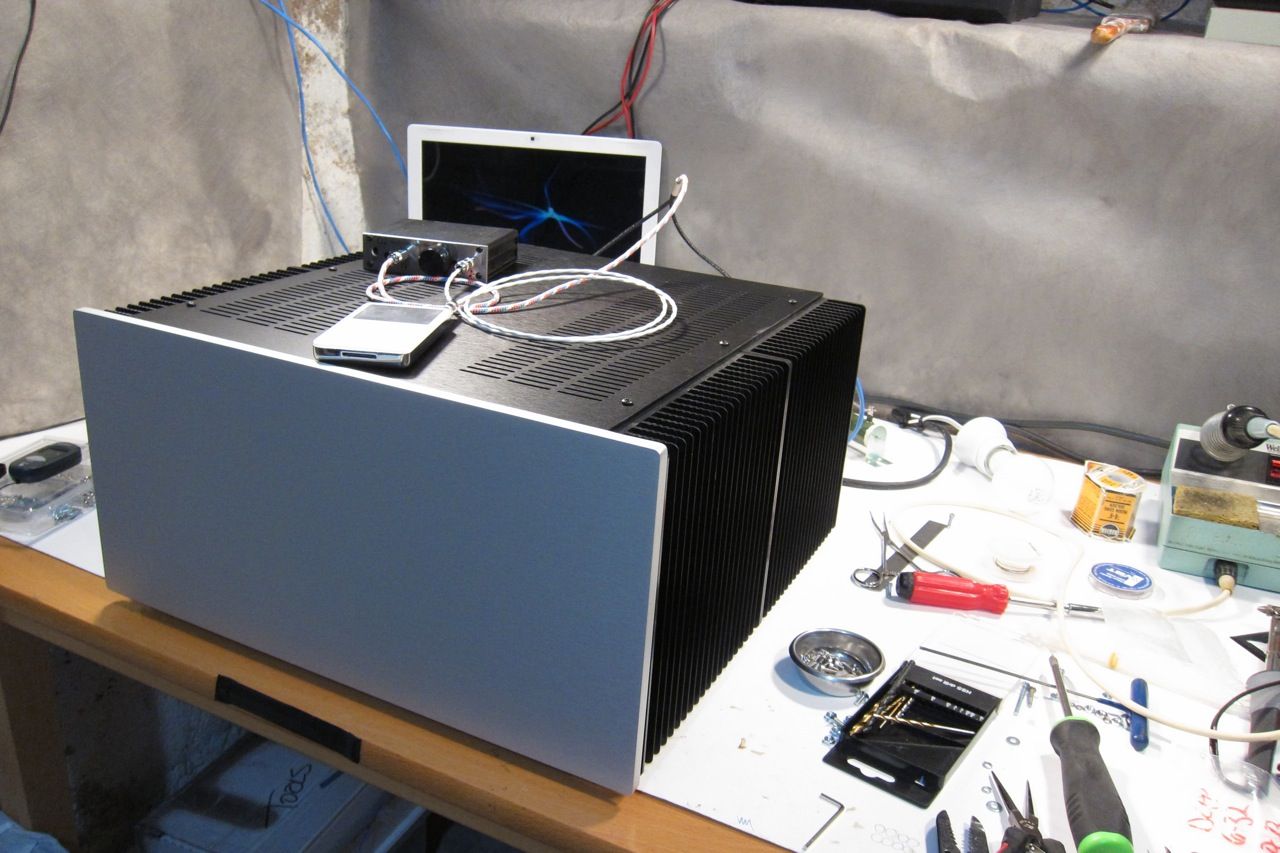
You can also see in these photos that the 5U 'Big Amp Chassis' is, in fact, as advertised, being quite enormous.
I used the 5U because I had it, and it will be used for a number of these guides. The 4U 'Jack of all Chassis' would be plenty for this amp.
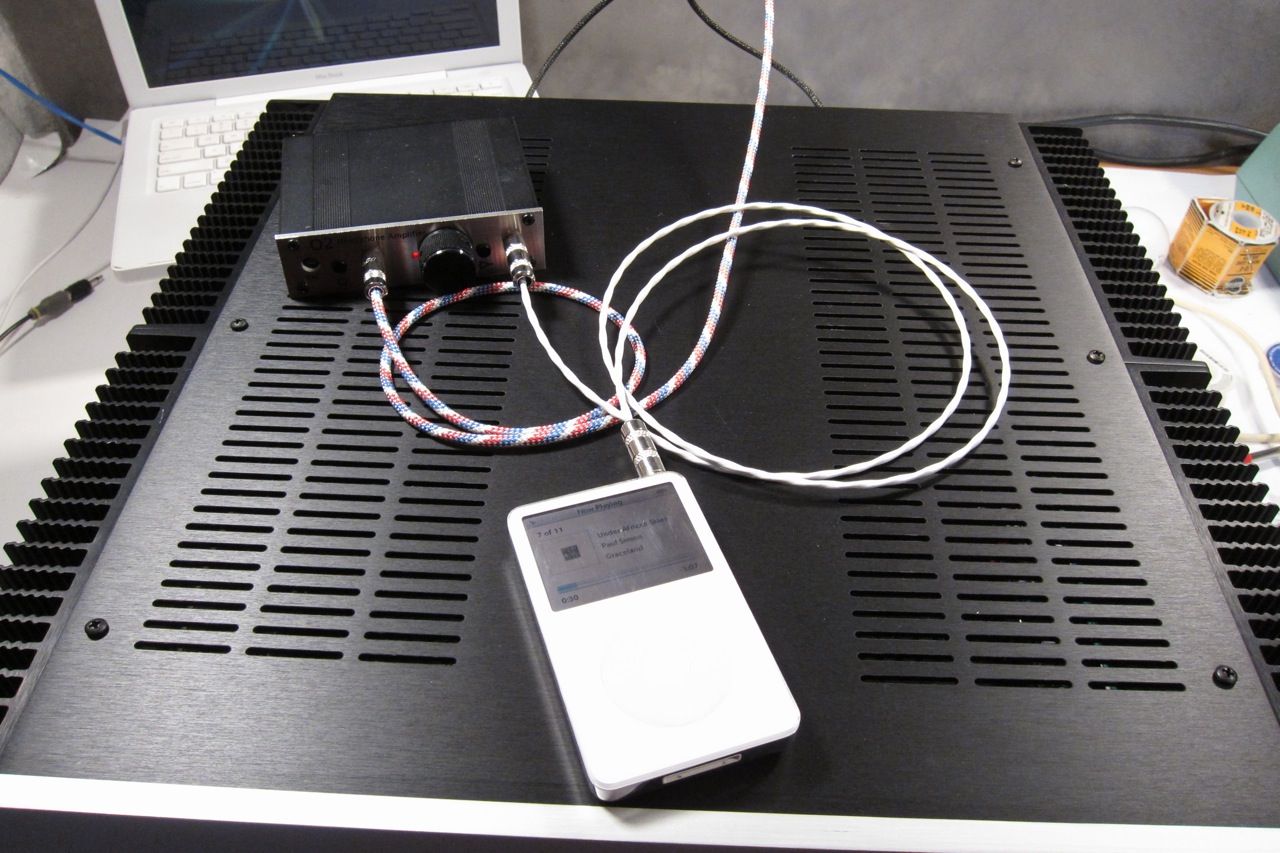
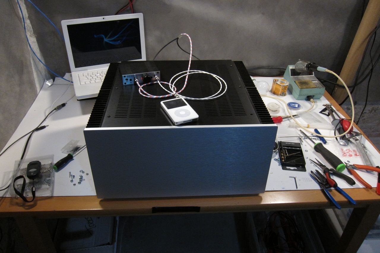
For now I am driving the F4 with an O2 Headphone amp, as it is the only 'preamp' I have that can swing enough volts (7) to give real volume, although not to clipping. Still, has enough drive for my current setup, so I'm not wishing for something else. It also sounds fantastic. Seriously.
An ImPasse will be built to drive this amp, and I am also very interested in the Pumpkin / Shunty.
So how does it sound? Well, there is not a lot to say because it's so incredibly neutral, it sounds a lot like the O2, which is very neutral and musical itself.
I have been finding the amp extremely difficult to listen to critically and listen to the amp, as I find myself singing along to whatever I play… Every time. It's really cool.
How does it compare to the F5? That's very hard to describe - you the F5 is a fantastic sounding amp, no question. Better than any other amp I have ever built, tube or SS. It (the F5) will make you understand the whole 'Class-A' mystique, and you will be very happy that you built it, because it delivers on it's promises. It truly is a great amp and a great design.
The F5, when compared to the F4 is, in my opinion, is a bit boring. The F4 is that good. . But remember it comes at a price, specifically that you will likely need a dedicated preamp for it. (Or you could bi -amp it with a flea-powered tube amp, but that's a different story. See the manual for more info.)
Some interesting measurements concerning bias levels -
Here are some quick and dirty measurements I did looking at various levels of bias on the F4. ( +/- 22.5V rails )
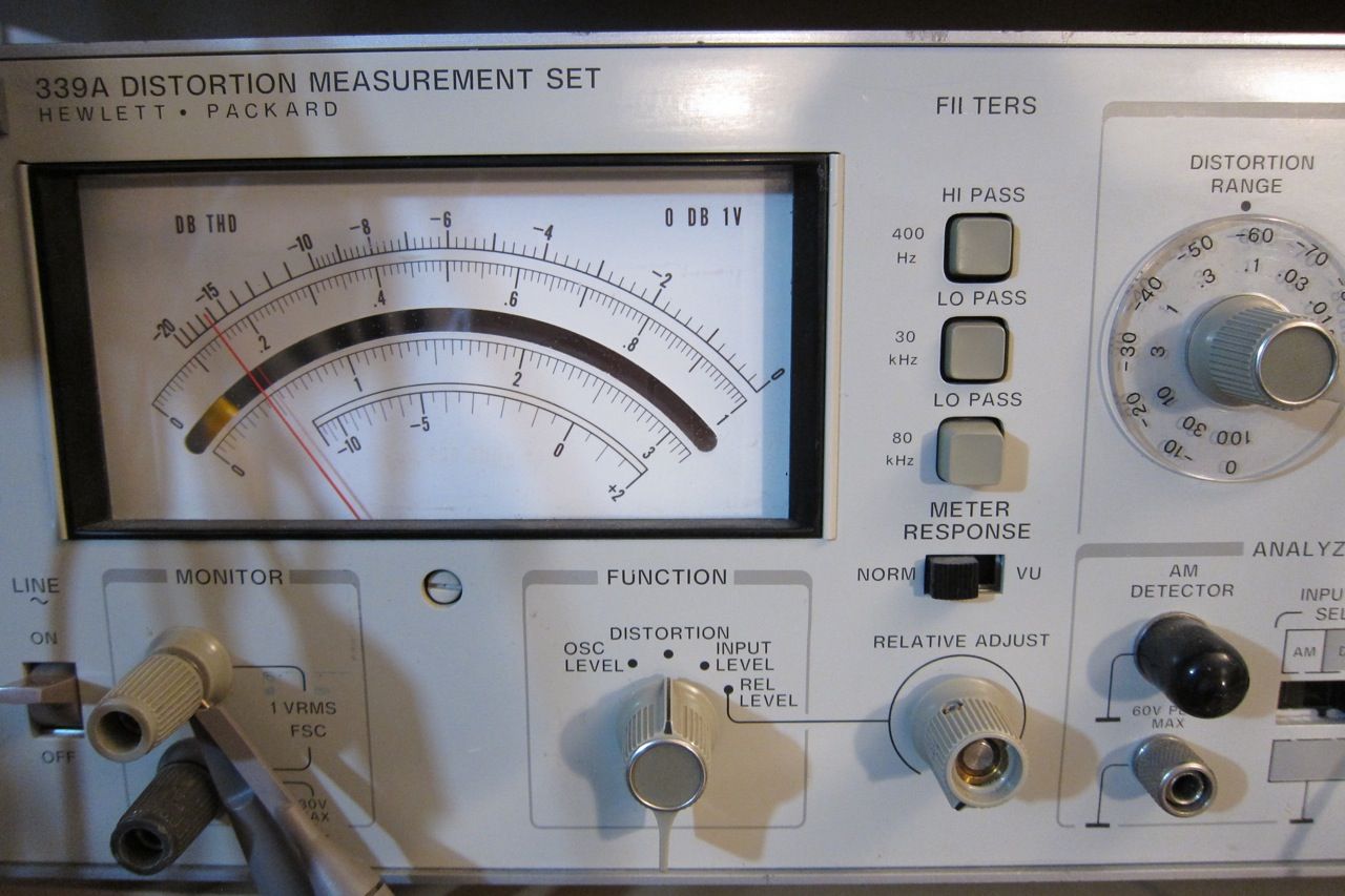
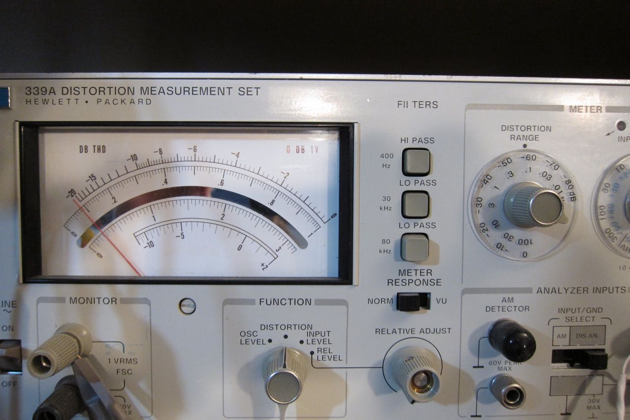
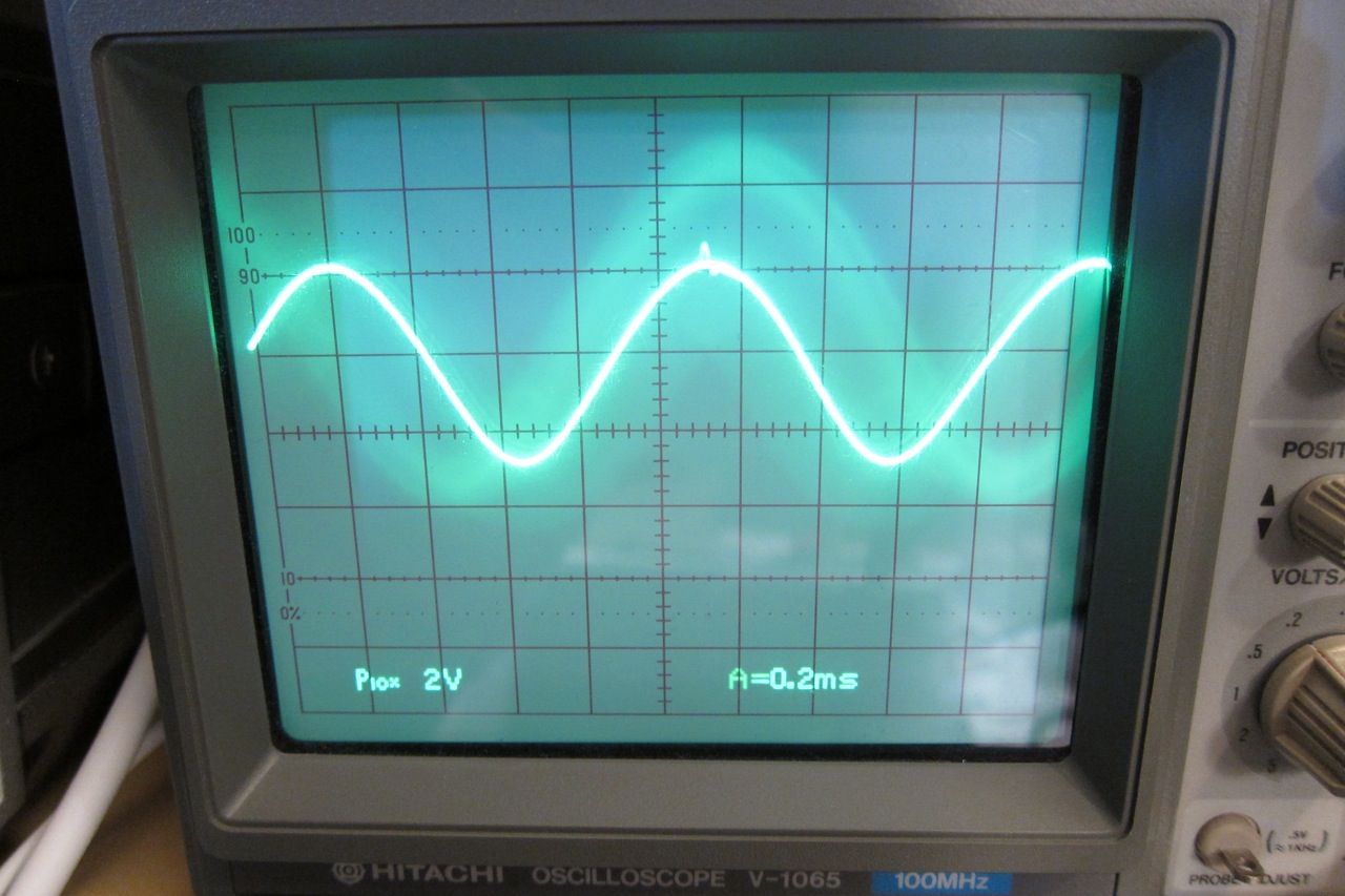
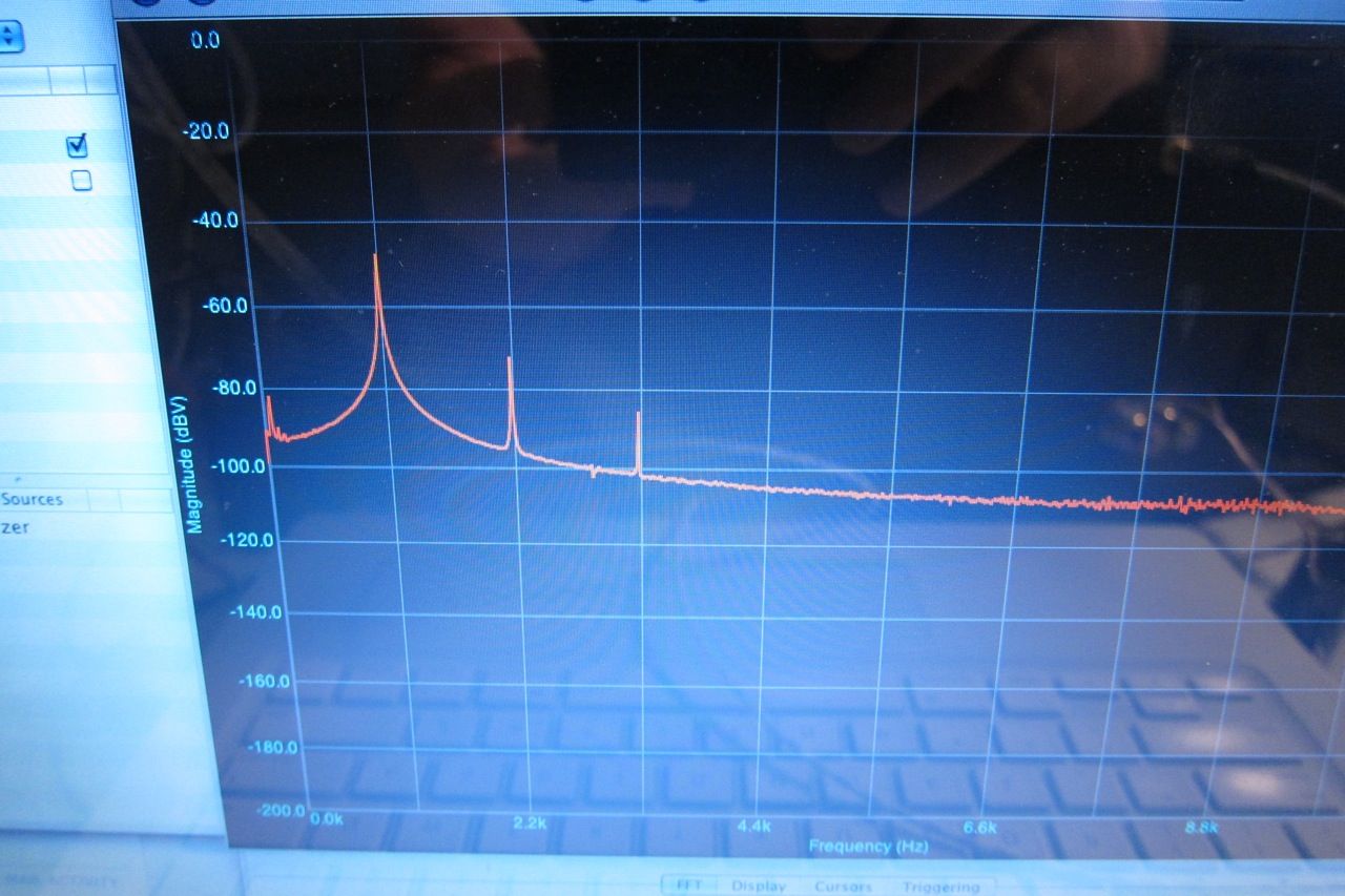
The conditions are, amplifier to normal temperature, one channel driven (because I cant read 2 at once), input to amplifier 3V 1.1kHz sinewave from 339A, distortion read across 4ohm 100W dummyload resistor, oscilloscope and FFT connected to HP 339A monitor, which was outputting the residual distortion waveform.
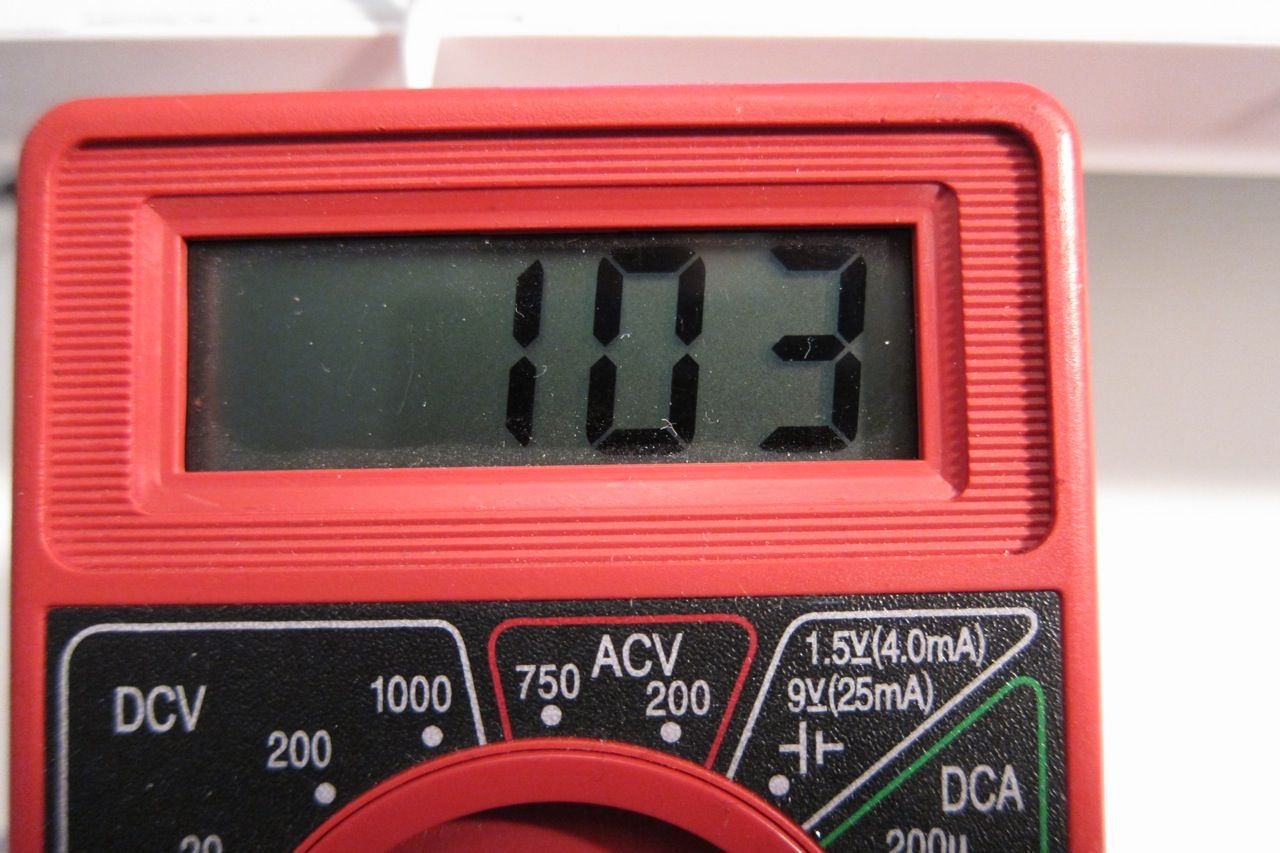
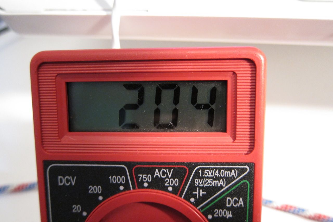
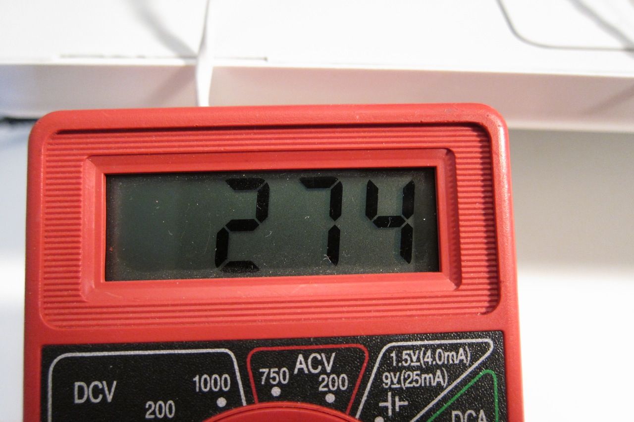
Bias measured across a .47 source resistor. (This is 1/2 the normal level, for illustration's sake)
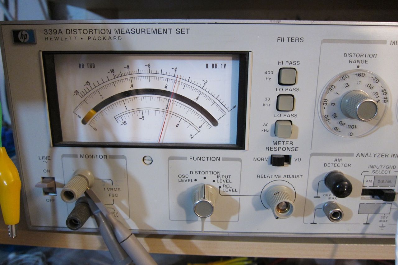
Distortion (Meter is set to the .1 scale, look at the arc above the mirror, here showing .065%)
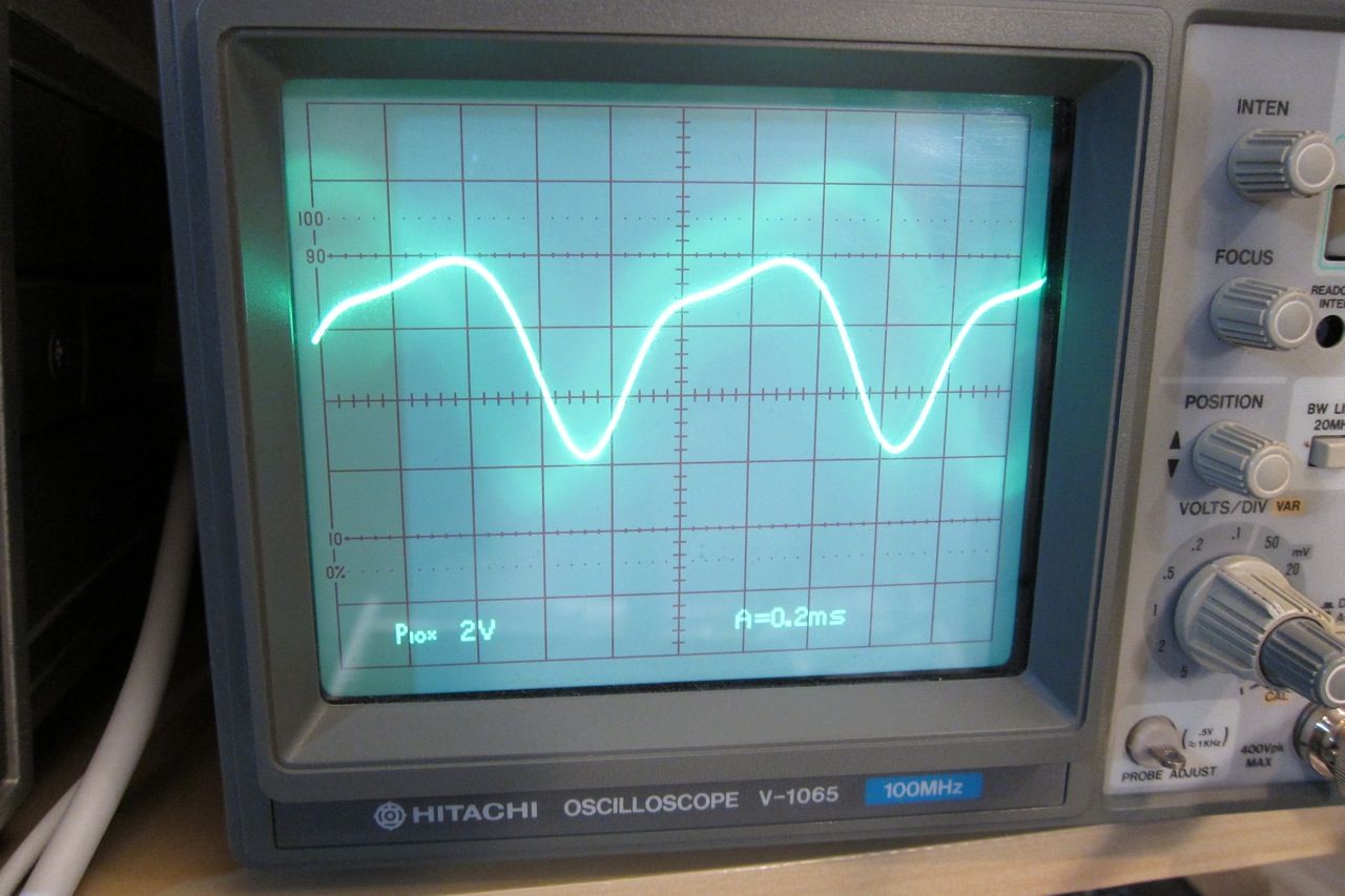
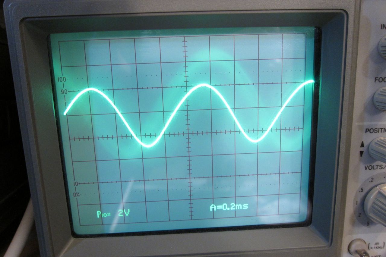
Here is the shape of the distortion residual. (No distortion would look like a perfect sinewave.)
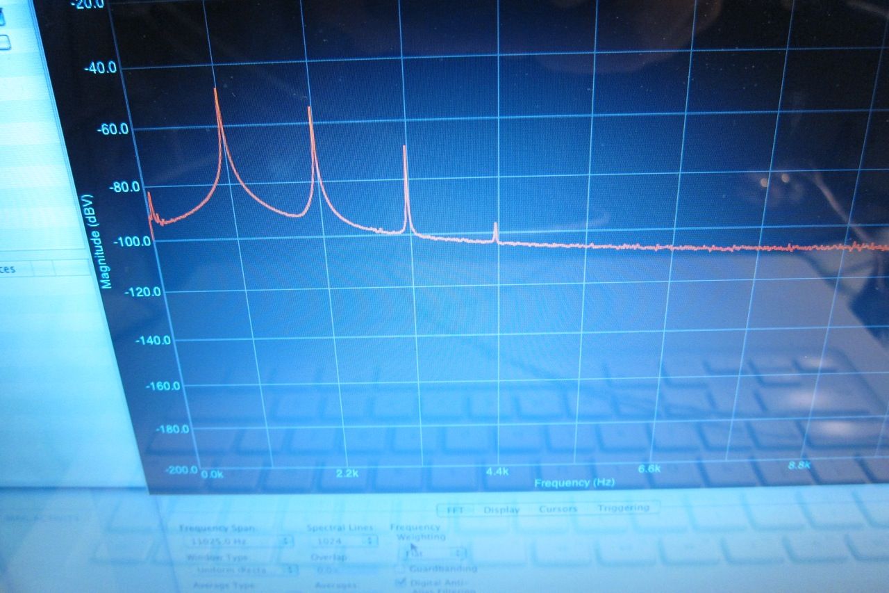
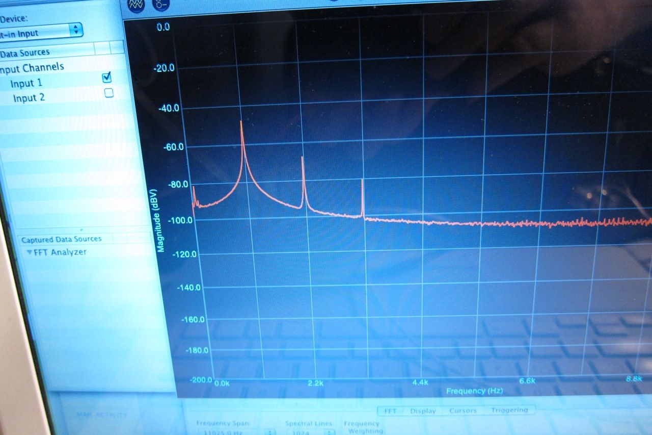
FFT of the distortion residual. (please excuse the photo of the screen. The next time I do this I will get screenshots.) The 1st peak at 2.2k is the fundamental. (2.2k chosen as it aligns with the gridlines. ) Looking right, he 2nd peak is the 2nd harmonic, the 3rd peak the 3rd harmonic, and the 4th peak the 4th harmonic. Higher level harmonics are not visible, as they are very small and lost in the noise.
Now let's increase the bias to the recommended amount, 200mv measured across the source resistors.
Distortion has now decreased to .016%. All that has changed is the bias. What a marked difference!
The distortion residual has lost it's humps and is looking very smooth.
The 4th harmonic is no longer visible, and the 2nd and 3rd are greatly reduced.
Increasing further -
Distortion now .08%
Residual very similar to above, but even more smooth. (A little bit, anyway…)
FFT showing the 2nd and 3rd harmonic even lower. Neat!
So the logical thing is to just crank it all the way up, right? Well, yes and no. Here are the reasons (and people with more experience please correct me if I'm wrong.)
1) Heatsink - at some point you are going to get too hot. With the 5U that wasn't an issue. A good rule of thumb is the transistors 65C max and heatsinks 55C max.
2) Bias current vs. VA of transformer. You don't want your total bias current (in watts) to be more than 1/2 or maybe 2/3 or your transformer's VA rating.
3) Transistor dissipation. Make sure you look at the datasheet for the output transistors, they all have an absolute maximum and a de-rating as they get hotter. For long life don't set more than 1/2 the max dissipation.
4) Point of diminishing returns. In this example the measured distortion continued to decrease (down to .045 or so) as bias was increased to 370mV, but the gains were very small and it would added lots of heat. The sweet spot was closer to 300mV bias.
Lovely work and I have heard this amp it is good but I am biased toward mine, but Nelson's work has always been great and inspiring. 🙂
Lovely work and I have heard this amp it is good but I am biased toward mine, but Nelson's work has always been great and inspiring. 🙂
what is "mine" please tell us about it.
Could you please stop this?...............PSU is currently 35V Panasonic 15Kuf caps for 60Kuf per... or I picked up some 35V Chem-Con at 56Kuf for 112Kuf per.................
Kuf is Kelvin micro fempto
You should be typing mF: milli Farad.
what is "mine" please tell us about it.
I know I'm not Colin but here's a couple of links
SECA KITS Diy
SECA KITS Diy
Sorry for of topic.
- Home
- Amplifiers
- Pass Labs
- A guide to building the Pass F4 amplifier