Pass DIY Addict
Joined 2000
Paid Member
Gotcha! I'm not super familiar with this set of boards. I do like those snubber boards that sit on top of the rectifiers, though!
^ I'm a big fan of Randy's PSU layouts. I also love the snubber / rectifier boards. If you haven't tried them... I gotta admit ... my absolute favorite little gem is the soft-start / safety cap boards.
I think low voltage amps can sound amazing, and I like this bias circuit, so I would like to try a combo.Why do you want to run one at such low voltage?

solve it with a CL-60 (or similar) between channel ground at the board level and AC mains ground at power entry.
@ItsAllInMyHead answered the question and I'm just adding a photo from Randy's build guide. Sorry I missed that in the massive photo dump.
Use alu bracket to lift 'clean' audio ground from 'dirty' PSU ground or connect direct to copper plate?
View attachment 1330439
Anyone know how "dirty" was the grounding scheme in the stock F4?Given the choice between aluminum and copper, I would choose copper every time.
my guess is the x-over implementation.
It was easy to hear it fall apart.
I had high hopes since I purpose built the F4 for exactly that role.
Not cheap but looks like a great way to implement two-way active crossovers. https://danvillesignal.com/dspnexus-dsp-audio-processor

Up next in my build queue: The F4!
Stay tuned! hehehe
Thank you again to 6L6, who's been a tremendous help to my incessant build fever!
.jpg")
Stay tuned! hehehe
Thank you again to 6L6, who's been a tremendous help to my incessant build fever!
DrDyna,
Good to see the progress on your build.
Another shout-out to 6L6 - Jim, thank you for putting together the detailed build guides, and being an active source of guidance and encouragement to DIYers on the forums!
Good to see the progress on your build.
Another shout-out to 6L6 - Jim, thank you for putting together the detailed build guides, and being an active source of guidance and encouragement to DIYers on the forums!

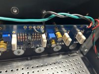
Got a small issue while trying to finish an F4.
testing one channel at a time. The first one I tried to bias starts out at 210mv but continues to climb up over 230mv and doesn’t stop. I will note that I added a 10k resistor in parallel to R9 during the build.
I checked all solder joints and they look good.
Psu Voltage is stable at +-22.40 Volts.
Any help is appreciated
Attachments
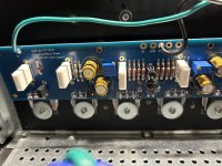
I would reheat each one from the top where we can see, heat for a couple seconds, and then add solder.
I just tried the opposite channel and it didn’t fire up as high as 210mv. It started up at 160mv but it did the same thing and kept climbing upwards.
I wonder if I have the wrong diodes in D2. I bought them at a local electronics store but could have grabbed ones not in the right location.
I wonder if I have the wrong diodes in D2. I bought them at a local electronics store but could have grabbed ones not in the right location.
- Home
- Amplifiers
- Pass Labs
- A guide to building the Pass F4 amplifier