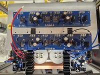
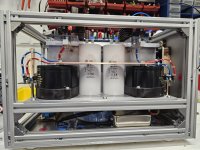
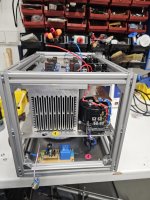
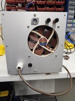
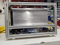
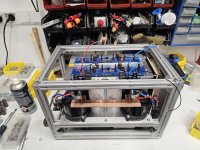
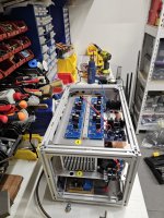
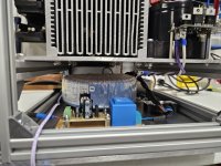
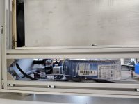
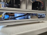
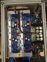
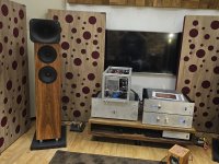
I committed to this project about 15 years ago. Still half-way through 
Hugging JFETs need to wait this autumn to see some electrons passing by...


Hugging JFETs need to wait this autumn to see some electrons passing by...
Pass DIY Addict
Joined 2000
Paid Member
Look at it this way, after 15 years, you are using bargain-priced parts! 😏
Dear Diyaudio Community.
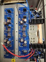
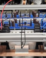
This is my Pass F4 balanced mono block Projekt.
Image shows one channel mono block
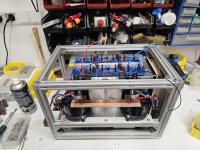
I need your help with constructing my F4 in balanced configuration.
What will be the best way to connect the ground of the amplfier boards to the PSU ground?
1. Green: each board with his own thick wire to PSU ground?
2. Red: shorts wire between boards and one wire from the middle of the connection to PSU ground?
3. White: shorts wire from one to the other board and then one wire to PSU ground?
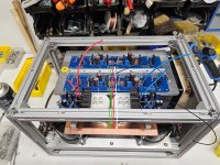
Should I 'lift' the 'clean' audio ground with an alu bracket a little bit from the 'dirty' PSU ground on the Chopper plate?
Or should I simply connect it direct to the copper plate?
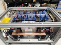
Thank you very much in advance for your help!
This is my Pass F4 balanced mono block Projekt.
Image shows one channel mono block

I need your help with constructing my F4 in balanced configuration.
What will be the best way to connect the ground of the amplfier boards to the PSU ground?
1. Green: each board with his own thick wire to PSU ground?
2. Red: shorts wire between boards and one wire from the middle of the connection to PSU ground?
3. White: shorts wire from one to the other board and then one wire to PSU ground?

Should I 'lift' the 'clean' audio ground with an alu bracket a little bit from the 'dirty' PSU ground on the Chopper plate?
Or should I simply connect it direct to the copper plate?

Thank you very much in advance for your help!
Last edited:
1. Green: each board with his own thick wire to PSU ground?
judging by pictures, you have wires to each cap to transfer pumping currents, while copper bridge is free of same currentsOr should I simply connect it direct to the copper plate?
so, exact middle of copper bridge is pretty clean, regarding pulsating currents
Hello, dear Diyaudio community.
I have another question about the ground connection. This time it's about the signal input.
But first I would like to give a few more details about my design.
The AC department is housed in the basement.
After the 230V input there is first an inrush current limiter, then a line filter from Schurter, then distribution to the toroidal transformers (500VA, 2x18 V from Sedlbauer) and an adjustable power supply (LM 317 based) for the heat sink fan.
The heat sink and the DC part of the power supply are on the middle level.
First LT 4320 based active rectifiers from @prasi, then a 100,000 uf electrolytic capacitor from F&T with film capacitor and bleeder resistor. Then a voltage regulator R21 from @tombo56 and then another 40,000 uf of elkos and an 80 uf motor run capacitor.
The amplifier boards are on the upper floor.
I use an XLR socket from Viborg for the signal input, and low mass copper binding posts from EIZZ for the output.
The amplifier boards are equipped with a few boutique parts - Shinko tantalum and Takmann Rey metal film resistors in the signal path, Isabellenhütte Manganin resistors as source resistors, WIMA MKC to bridge the electrolytic capacitors in the signal path.
The start-up procedure ran without any problems, the voltage regulation of the PSU works perfectly, I have so far adjusted the quiescent current to 250mV voltage drop across the source resistors - this gives me a heatsink temperature of just 40°C with 2/3 fan speed and 25°C room temperature.
These heatsinks really work great! I found them from a local manufacturer (Alutronic, model PK 717/300).
What is the best way to connect the ground connection of the input signal?
1. One connection to each amplifier board (green)?
2. A common connection to an amplifier board (red)?
3. A common connection to the copper plate of the power supply (white)?
4. Or something else?
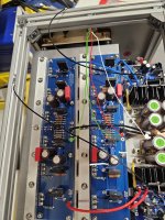
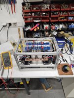
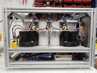


Last edited:
Wired mine to handle both RCA SE operation as well as balanced monoblock I connected:
a. each RCA grnd to grnd on board for respective channels
b. XLR grnd to grnd of only one of the boards. (flipped a coin)
If I remember correctly, I tested continuity between signal board grnds and found them connected (assumed via the PSU grnd on the boards). Easy to test.
I went with as few grnd connections as possible to avoid loops. Not sure it is the most correct way but I haven't had any hum issues.
I have the stock F4 and want to use it in its balanced mode to drive a center channel speaker. I don’t have the speaker yet but expect it will be ~ 90db/w/m and I will probably never play it much above be 65db at SPL at ~ 11 ft away in a ~2700 cu ft room.
Under these conditions will the F4 get hotter than it usually does in unbalanced stereo mode? In any case, given the balanced mode’s humongous 100 watt output, can the F4’s supply and/or bias be turned down for energy savings and a lot less heat?
I know some may consider that a LOL question but if doing so doesn’t appreciably increase distortion or reduce frequency response please describe the procedure to do this.
There is no increase in heat when used in mono.
Yes, you could turn down the bias if you want. I personally wouldn't. YMMV.
Yes, you could turn down the bias if you want. I personally wouldn't. YMMV.
But why not if distortion, noise and frequency response won't suffer?There is no increase in heat when used in mono.
Yes, you could turn down the bias if you want. I personally wouldn't. YMMV.
- Home
- Amplifiers
- Pass Labs
- A guide to building the Pass F4 amplifier

