F4
Would a antek 4218 transformer enough for mono block F4 ? Or do I need softstart if replace by antek 500 KVA .
XLR mono 100W 8ohm and 4ohm power will be 50w ?
Best Regards
Myint67
Would a antek 4218 transformer enough for mono block F4 ? Or do I need softstart if replace by antek 500 KVA .
XLR mono 100W 8ohm and 4ohm power will be 50w ?
Best Regards
Myint67
I would double check your resistor values and solder joints.
agree
Would a antek 4218 transformer enough for mono block F4 ? Or do I need softstart if replace by antek 500 KVA .
XLR mono 100W 8ohm and 4ohm power will be 50w ?
Best Regards
Myint67
I used the 4218 and its is wonderful.
I didn't even bother with a soft start circuit, I just used the thermistor like the F4 manual shows.
F4
Thanks Einric
I used the 4218 and its is wonderful.
I didn't even bother with a soft start circuit, I just used the thermistor like the F4 manual shows.
Thanks Einric
I would double check your resistor values and solder joints.
Checked resistor values. I had a 27.5K value in R8 instead of 22.1K Replaced it.
All other values are good.
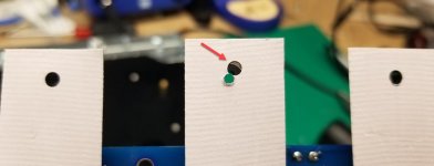
Check out the Mosfet pad shown in photo. I'm surprised this didn't result in a short.
Done for tonight.
Attachments
Forgot to mention that I'm working on the Left channel, as that is the one that has lower volume than the right.
check for uniformity:
-torque of mosfet screws
-voltage at/across all source resistors
re-check all solder joints
F4 is damn follower, if you have lower output - it's either problem with pre (swap channels test) or trivial problem with interconnects/contacts or ......... Gremlins
temperature issue - hope it'll be clearer when you check all source resistors
Chiptech,
Did you measure the voltage across ALL of the source resistors as Zen Mod asked? Perhaps your mosfets are not as matched as you had expected.
Chiptech,
I don't think R8 will change the volume. It affects the voltage range
in the bias circuit so you will need to adjust that channel again.
I don't think R8 will change the volume. It affects the voltage range
in the bias circuit so you will need to adjust that channel again.
Chiptech,
Did you measure the voltage across ALL of the source resistors as Zen Mod asked? Perhaps your mosfets are not as matched as you had expected.
Ok.
Here are the bias readings:
R16 - .158
R17 - .181
R18 - .189
R19 - .179
R20 - .187
R21 - .163
It appears I have some variance. What would we normally like to see?
It is best if the three mosfets in each phase (positive and negative) are matched as close as possible. So swap mosfet from R16 with mosfet from R20 will get you better matching.
Since you said that the other channel, the right channel, is louder and hotter, measure the voltage drop across all of the source resistors there too to compare. If it is running hotter, it could be running higher voltages and therefore higher current.
Since you said that the other channel, the right channel, is louder and hotter, measure the voltage drop across all of the source resistors there too to compare. If it is running hotter, it could be running higher voltages and therefore higher current.
Well my thought is that if there are variations in the mosfets and if the bias is based on one source resistor, it can happen that one channel is based on the low mosfet and the other channel is based on a high mosfet.
For best match between channels, measure all three source resistors in a phase and take the average voltage for the bias.
For best match between channels, measure all three source resistors in a phase and take the average voltage for the bias.
Ben Mah and Zen Mod, thanks for your counsel.
Learning a lot here.
I will follow your guidance and report back.
Since it's averaging 114 here for the last week, it's good to have a project.
Chip
Learning a lot here.
I will follow your guidance and report back.
Since it's averaging 114 here for the last week, it's good to have a project.
Chip
It is best if the three mosfets in each phase (positive and negative) are matched as close as possible. So swap mosfet from R16 with mosfet from R20 will get you better matching.
Since you said that the other channel, the right channel, is louder and hotter, measure the voltage drop across all of the source resistors there too to compare. If it is running hotter, it could be running higher voltages and therefore higher current.
R16 thru R18 are N Mosfets
R19 - R20 are P Mosfets
I don't think I want to swap R16 [N] for R20 [P]?
- Home
- Amplifiers
- Pass Labs
- A guide to building the Pass F4 amplifier