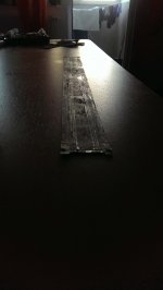
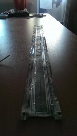
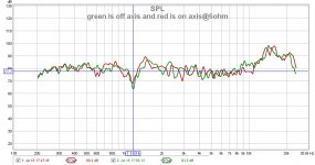
I dissasembled ruban 4 ( the one with foil former) to see what went wrong. So here we are. In the pics bellow we can see the flatness of the coil on the syde where the glue sticked evenly, with a very good bonding, and in the second pic we can see the actual problem: glue everywhere... This situation makes a huuge dip at 1khz region and resonances wich you can hear for shure at high volume levels.
So be carefull people when the gluing process is done!!
Cheers
Sergiu
So be carefull people when the gluing process is done!!
Cheers
Sergiu
Attachments
My first attempt
This thread is turning into a tome, but the subject is great and got me started on my own version. It's very much a prototype at this point that I've dubbed the Kaptonoid as it is made with kapton tape. It makes noise and frankly is much better than I expected given the hashed-up nature of this proof-of-concept build.
I've set it up for full time tweaking and will report more (maybe in a new thread?) as it progresses.
I greatly appreciate all the work everyone has done here and will do my best to return the favor!
Attachments
Congrats snotwagon,
I really appreciate your interest, BUT the magnets arent supposed to be arranged like that (please show us some more detailed pics here).
Another aspect is that you have to tweak the cilinders allot...
I wanted to try kapton or mylar too but couldnt find a supplier in Romania...
If you have a mic please measure you results and report back.
I wasnt lazy either; i made another ruban with a different coil and will post my results tomorrow. I can make my measurements slower now because we entered in full season at my job and we have allot of orders and i'm abit late home.
Cheers
Sergiu
Hello my friend, Wrine,
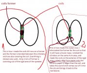
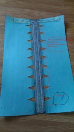
I have tested another type of positionning for the coils. Instead of positionning them insyde the rigid area of the membranes it made the coils outsyde. Look at the painting i made to show you bellow. I attached a pic with the actual membrane bellow and the measurements.


The sound, well when listened to it sounded like a very very good speaker. This type of coil arrangement, when foil is used for the cilinders, its neutral and the sound its like comming from the speaker (the other versions where like sound projectors, where you could barelly locallyse the speaker). I think you will like this version Wrine, because you wanted to bee able to locate the speaker in the room, and this version does it with succes. I think this is what you searched for.
For me, well i really miss the live concert effect that other versions had so i will digg more. Will try a paper membrane for this version too.
Cheers
Sergiu
I have tested another type of positionning for the coils. Instead of positionning them insyde the rigid area of the membranes it made the coils outsyde. Look at the painting i made to show you bellow. I attached a pic with the actual membrane bellow and the measurements.
The sound, well when listened to it sounded like a very very good speaker. This type of coil arrangement, when foil is used for the cilinders, its neutral and the sound its like comming from the speaker (the other versions where like sound projectors, where you could barelly locallyse the speaker). I think you will like this version Wrine, because you wanted to bee able to locate the speaker in the room, and this version does it with succes. I think this is what you searched for.
For me, well i really miss the live concert effect that other versions had so i will digg more. Will try a paper membrane for this version too.
Cheers
Sergiu
Attachments
-
 new type of ruban.jpg111.2 KB · Views: 741
 -
 IMAG0206.jpg373.7 KB · Views: 745
 -
 9th ruban@ red is on axis@ green is off axis.jpg120.3 KB · Views: 123
 -
 on axis with cuts @green =between the cuts@yellow=insyde.jpg112.9 KB · Views: 136
 -
 on axis@red=no cuts@green =between cuts.jpg121.9 KB · Views: 153
 -
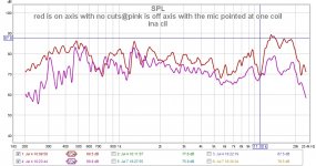 red is on axis with no cuts@pink is off axis with the mic pointed at one coil ina cil.jpg135.7 KB · Views: 120
Thanks, Sergiu:
I think you're looking at the little button magnets I used for securing the opposite sides of the membranes. That was a bad idea and I am working on a new method. I'm also working on improving the membrane winder so I can make nicer membranes.
I have an updated version built that is better, but still needs refining.
How are you measuring frequency response? What software and where do you place the microphone with this type of speaker?
Thanks,
Jerry
Hi snot,
I make my measurements with the mic at 0.50m from the speaker to really see whats hapening out there and at -23,4~-23,6dB volume all the tine in REW. I make an on axis measurement with the mic pointing at the center of the speaker, where the cils meet and off axis at exactly 45degrees pointing at the 3cm area near the center joint (the active area 😀).
I usually use REW and ocasionally Holmimpulse to verify if i'm good with the measurements, combined with an electret mic+a diy almost flat frecv mic preamp and a phantom supply+ JLH69amp hooked to a calibrated soundcard from my pc.
Cheers
Sergiu
Ps: usually i've seen all the rubans till now with the magnets being sandwiched between steel plates thats why i asked how is you motor assembled... Please post some measures pics if you can.
Hello Wrine,
Are you still there, or quitting?
Today i found a extremely interesting thing on the long therms issues. Remember that the coil tends to bend in time from allot of factors , so i searched for a sollution : first add a thin layer of laq on the membranes on both sydes before sticking the coil then center the membranes in the gap so that they will move freely,with no rubing when touching them, and this is a very very important : dont add elastics on yet.Add the elastics when its finished and centered. Very good results where obtain with this methis in ling and short term.
Cheers
Sergiu
I want to add another thing to the laq coating: the total surface that needs to be coated with one thin layer of laq on the interior of the cils where they bond and exterior (insyde the them) is on the total hight * 15cm then add another coat exactly onto the back of the coil, on the 3 cm area (all of it). This adenum doesnt influence the sound, it only makes the paper insensitive to moisture and make the paper abit more ferm. Bare in mind that i didnt add laq to saturate the paper, i aded only a thin layer of well speaded laq.
Remember, this is only for the paper users!!!
Cheers
Sergiu
Ps: i came back to the paper membrane because to my ears this gave the best sound signature and realism...
Remember, this is only for the paper users!!!
Cheers
Sergiu
Ps: i came back to the paper membrane because to my ears this gave the best sound signature and realism...
Hi guys ,
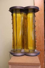
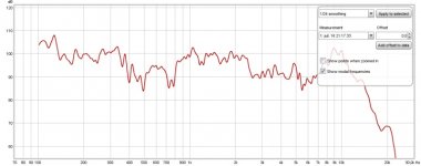
I finaly got the "UMIK-1" i ordered at AUDIOPHONICS , I use it with REW (your prog Sergiu). I'ts simple to use the Umik is an electret with integrated preamp and line in soundcard plugged to laptop by USB, but i think i have to calibrate the output of my laptop soundcard for getting an accurate trace after 10khz . Anyway here are my fisrt results : the curve shows the performance of
output laptop soundcard+tube power amp+filter +boomers+Janus.
here it is :
Attachments
Well hello Michel,
I'm glad you came by here 🙂.
I'm glad that you buyed the umik, because with separate things like i have used its complicated... First thing to do now is find a calibration file on the producer site or the net for your mic. Then enable 24bit audio on win 7 or the operating sistem that you use, then enable 24bit@192khz in REW. Be ware that these steps are crucial. If these steps are accomplished you can really see how far your rubanoide goes to the 20khz....
First thing that i see is you have the same problem as we did at the begining. We didnt enable 24bit from win7 and REW and our microfones didnt measured higher than 17~18khz. Please do this thing so that we can see what your ruban really outputs.
Cheers
Sergiu
Ps: i love the collor of your ruban. 😉
Your right i also find REW very easy to use and practicall. As your graph goes till now i see that you will have that 12-20khz peak too.. 🙂
Please do a cal. And enable 24bit to see.
Please do a cal. And enable 24bit to see.
Thank you for the trick Sergiu :
my soundcard is mutch better in 24/192 but there is still a lack in highs from 12000 ...
(hopefully i don't hear anymore beyond this frequency!lol)
I agree totaly with you about the sound of paper
cheers
MP
Now we're talking. 🙂 Believe me, even if you dont hear further you will still be able to perceive the presence of higher frecv responce (if there is) as finess, and a more detailled and sweet sound (i'm not joking).
Even if i post very few things from two weeks ago till now that doesnt mean i didnt do anything. I rebuild 5 rubans from scratch all these two weeks till now, and this time i make subjective tests and taking notes (instead of measurements) and post here only the mods that i consider of making the most important modifications to the sound and reliability (subjectivelly speaking and practicall tests).
And let me tell you what i do now. Within a week i make 2 to 3 rubans and invite two friend of mine at my place, one is a drumer in a band the other is a violin player, and me and my wife and within 3-4 hours, each saturday i make modifications and i listen with them to each mod, and the most interesting part is that the best ruban versions are the worst in measurements. 😕😱
To me and my friends all of our votes goes to the single coil and a single soft elastic bended in two for up and down, and its a strange thing because its contrary to the measurements made (look at a single coil version that i listened and measured yesterday with a single coil where we all agree that sounded best). I'm still experimenting with coils, on how much turns they have to had and the cuts insyde and outsyde the the coil... One thing its for shure for a very good sounding ruban receipt: you need allot of cuts, laq, less super glues and a small mass coil and membrane or a special foil like PVF film or tedlar wich have special bending propreties...
Anyway please tell me what coil do you use, foil printed, flexible pcb or diy Al coil like i did?! And please describe how you bonded the coil (what are the contact surface dims), where did you put laq and super glue and how big the cuts are and how much cuts did you did in the membrane. Maybe i can help you improve the hights.
Cheers
Sergiu
PS: my ears are still sensitive and let me tell you why: when i was a child i putted in my years plugs of cottone for protecting me from cold and winter but i forgot to take them out... Time passed and forgott about them. then after allot of hearing only mids and very few hights and bass (i thought i had a disease) i went to a doctor two years ago to unplug my ears. So what do you now, today, after two years i can still hear up to 18khz (if i concentrate).. 🙂
Attachments
Anyway please tell me what coil do you use, foil printed, flexible pcb or diy Al coil like i did?! And please describe how you bonded the coil (what are the contact surface dims), where did you put laq and super glue and how big the cuts are and how much cuts did you did in the membrane. Maybe i can help you improve the hights.
Well, looking at your curves and mine i have a possible explanation for the response after 12000 hz : too loud for you , roll off for me ...
The major difference beetween us is: my coil is 2X10 = 20 turns yours is 3 ! independently from the mass characteristics (copper /Al) The inductive property of the coil probably has a significant influence on the frequency response in the upper band .
I will try to plug my coil in parallel (10turns) so the inductive value will be half and we'll see how the curve is . Have you ever use coils with more turns ? did it flatten the upper response ?
Hi Michel i have tried paralell coils for a long time, and series too> First there was single coil like now, then series and after it was paralell... Yes paralelling will flatten the 12-23khz. Let me look and i will show you.
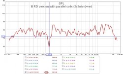
Here it is. The paralleled coils version. It has 2x8 ohms summing a total of 4 ohms in parallel. The problem of the paralell is that the dip from 1,1khz goes deeper down. And i can assure you that on this version (IIIRD) wich is made from foil you can really perceive the lack of mids when cranking up the volume....wich is weird.
I think that the dip from 1.1khz is in fact the region where the coil stops moving and beginining to vibrate to produce sound for the upper spectrum, and because of the hight of the cilinders the recovery time is bad here. Interesting thought is that you dont have this dip. Wrine had this dip too if i remember correctly.
I had this dip on the single coil also from the paper ruban but i couldnt perceive it at all, subjectivelly speaking. Odd things..
Attachments
Here it is. The paralleled coils version. It has 2x8 ohms summing a total of 4 ohms in parallel. The problem of the paralell is that the dip from 1,1khz goes deeper down. And i can assure you that on this version (IIIRD) wich is made from foil you can really perceive the lack of mids when cranking up the volume....wich is weird.
I think that the dip from 1.1khz is in fact the region where the coil stops moving and beginining to vibrate to produce sound for the upper spectrum, and because of the hight of the cilinders the recovery time is bad here. Interesting thought is that you dont have this dip. Wrine had this dip too if i remember correctly.
I had this dip on the single coil also from the paper ruban but i couldnt perceive it at all, subjectivelly speaking. Odd things..
Please excuse my nonsense from above (i bolded up this moment). I didnt erase this post because i wanted to show others that i am mistaking here so that they WOULD NOT do the same.
The actuall phenomena is not the nonsense that i told up here , the real deal is all in the cuts and i rereaded my notes from the begining of my journey (when i didnt had a mic yet) with this speaker and i will write here from my notebook (this can be tested for shure and confirmed by everyone): to perceive the sound signature, hights and presence and soundstage made by the paper material used for the cils you have to have cuts, and allot of them, insyde and outsyde the coil. In the center of the coil i have found that 20 pcs at 8mm diam is sufficient to perceive more hights and better dinamics and responce. The thing about these hights is that i strongly think that the speaker produces allot of them but they remain traped insyde the cils, BUT making cuts will make the coil & membrane sprout them outsyde . And later, in my measurements i have found that if you remove too much from the coil surface and membrane rigidness the peaks and dips of the frecv responce reproduced will be all messed up. You see, you have to have mass because you need to keep those peaks donw, but the membrane has to bee light to have cuts, and is very important that the mebrane to be stiff but flexible in the same time to tame the peaks. That is the key and most important aspects and propreties that the membrane has to have. Cutting 5mm by 3 cm from above and bellow from membrane on the top and bottom of the coil doesnt do much, only lower mass and may contribute to the overall fast response.
The exterior cuts are like a "delicate thing" for this speaker because they influence presence, sound projection, finess, the voice and the hights+dinamics. If you make the cuts more deeper into the cils than 8 mm from the coil (lets say 1 mm) you wil perceive a huuuge amount of hights and a very thin and low dB voice in intensity, but when you make them at a greater distance lets say 1 cm dist from the edge of the coil (the exterior or last turn) you will perceive the voice laid in the back so no more presence and sound projection (it will became like an ordinary speaker). The optimum distance where the cuts have to start is somewhere between 3 to 6mm max. MY CUTS FROM IIIRD VERSION STARTS FROM 3 MM INSTEAD OF 6 MM LIKE MY PREVIOUS VERSIONS AND THIS ASPECT MADE THOS DIPS GO LOWER NOT THE C**P THAT I TOLD EARLYER. This is all the fuss about the dist between the cuts and the coil.
Now the cuts: if they are too big the voice will bee too thin. Also the rigidity of the coil will be weakened and will start rubbing on the plates.
If they are too small you will perceive more voices but you will not want to go too small because you will want hights too. So the sollution is somewhere in the middle. I have found that triangles dims wich was best for my 120gr/sqm Canson CA Grain paper (2.2.....2.4cm base*3.5cm height). I didnt tested further with small cuts like yours Michel but i think that this is why you dont have that dip at 1.1khz...
To prevent the coil bending in the gap you have to spread a thin coat of laq onto the membrane (16cm centered with the axe of the coil) on both sydes and then spread another coat on the interior of the cilinders on 4cm width by 51 cm (height of my actuall ruban) centerd to hardened the coil.
Now i'm into a slowly experimentation process with the coil (bonding, turns). The best sound signature that i found for this speaker till now is with and overhung coil and not underhung (contrary to measurements). This increases the upper bass responce and makes the voice more round. With this type of coil this speaker rises the hair on you spyne and blow you away. You will not only hear the music instead you will feel the music, and this is just stagerring (i didnt heard this before from any speaker)...
Will have to experiment more here and i think that bigger contact surface is very important.
Cheers
Sergiu
Thanks for your long response Sergiu, i've red it with the utmost attention, your research about this speaker is quite a doctoral thesis and i'm serious
Let me ask you some questions please :
I don't understand the idea of transition "mooving to vibrating state" that allows you to explain the 1khz deep... do you mean the moment when the membrane mooves from "piston" to "fractionned vibrating" mode ?
if yes , this is more a question about the mecanic properties of the wings yours are 120g/m2 paper mine160g/m2 : heavier but stiffer
I've read your conversations with Wrine from the beginning one thing i don't catch too is the "underhung overhung thing" can you explain please ?
About the coil : I speak "turns" and you speak "ohms " so please let's speak about both : how mutch turns has your coil?
my coil is 2 X 10 turns and about 9 ohms of ohmic resistance. no idea about the real impedance
i will post my curves with 10turns in parallel soon
Cheers
Michel
Thanks Michel, Wlowes,
Please let me quote again what i've said before :
"Please excuse my nonsense from above (i bolded up this moment). I didnt erase this post because i wanted to show others that i am mistaking here so that they WOULD NOT do the same.
The actuall phenomena is not the nonsense that i told up here , the real deal is all in the cuts and i rereaded my notes from the begining of my journey (when i didnt had a mic yet) with this speaker and i will write here from my notebook (this can be tested for shure and confirmed by everyone)........"
This hapened because i wanted to edit post 856 but tooked more than 40 mins to read from my notebook, remember other stuff and then write my ideas down here, so this site didnt let me reedit so i posted in another new post the corected ideas (post 857).
What i wanted to say is that we can see in my old posts with measurements those dips got bigger in two cases: when you do the externall cuts too big too close the coil or the coil is not perfectly bonded to the coil. In my case first theory is valid (cuts too close to the coil).
The bonding process is very important too in a way that it influences the sound signature also. If you stick the cilinders directly onto the coil surface (3cm*51cm) you will perceive allot of hights because the edges of the coil are almost near to the point where they are nearly exposed (or almost). If you burry the coil insyde the cilinders (if the coil has former) the sound will be restrained and you will not have "presence anymore"; in the case of coil on former, after almost 10 pcs of rubans made and tested and heard, i can say that the best sound signature and voice clarity and rithm was with the former bigger (the former needs to have 4.4cm by 51cm instead of 3cm by 51cm like my first versions) and abit exposed at the same time, and with "exposed" i meant that you have to stick the cils only on the 4 cm area (centered) and leaving the 4 mm outside the rigid area (2 mm on front and 2 mm in the back AND NO MORE). Making the former bigger will create a separation effect [(and a really strange sound on axis like an inbalanced sound between two separate channels i may say) like in the case when your putting a big thick cardboard in front of your 15" bass speakers and you move from left to right in the listening room(you know what i mean)] and making the former exactly on the dim of the coil will make you perceive a strange effect/influence on the hights and voices (the voices and hights tend to sound like they shout, more like nasty resonances altought they didnt measured bad) when you crank up the volume (i measured this with my mic and it seems that i have only an increase of about 1-2dB in the 12 to 20 khz region where i allready have that nasty peaks). Making the former bigger in height (then 51cm) than the cils causes a restrained like sound if you apply too much tension on it but if you use thinner elastics and dont tension hard, the measurements are the same and the sound is same and its easyer to make it stay centered (i still have this variant and will play with it abit more).
In the "coil made dirrectly on the cils" (make the coil onto a cil then stick the other cil on the coil cil with no former) the cils need to be bonded onto the 4 cm area (centered, 5mm and 5mm in the fornt and back) to get that sound signature that i like most and wich blows me away.. If you expose the vicinity of the coil too much you get "shouts" at hight levels and if you make the bonding more than 4 cm the presence fades away milimeter by milimeter aded in plus (its like you are leaving your parents home with your car and they still say goodbye and you hear them litle by litle as you go away 😀)...
Now that this aspect is also solved let me answer you questioons Michel in you post:
"I don't understand the idea of transition "mooving to vibrating state" that allows you to explain the 1khz deep... do you mean the moment when the membrane mooves from "piston" to "fractionned vibrating" mode ?
if yes , this is more a question about the mecanic properties of the wings yours are 120g/m2 paper mine160g/m2 : heavier but stiffer
I explained this with a quote at the begining of this post. If you're playing the rubans in full range for tests you will perceive with your eyes, when played a full test sweep 100hz to 24khz from REW that the cils moves when reproducing low range and stops moving when going into the higher spectrum and starts vibrating (not seen with the bare eye but can be muffled if you touch the cils ahrd with a finger). The region where the ruban stops moving and starts vibrating is in the 1khz to almost 2khz area (i tested with a continous sweep from REW and watched and touched the cils)...
I've read your conversations with Wrine from the beginning one thing i don't catch too is the "underhung overhung thing" can you explain please ?
By underhung i meant a smaller coil (2.6cm ext by 1.4cm interior) and overhung bigger (3.3cm ext by 1cm int) . Underhung will tend to have an constant impedance in all spectrum when the coil stays in the gap and overhung tends to have a messy impedance curve in full range when the coil moves hard and is leaving more turns outsyde the gap
About the coil : I speak "turns" and you speak "ohms " so please let's speak about both : how mutch turns has your coil?
Very very thin Al (backing foil from the grocery) used for low mass@3 turns at an average of 1.8mm width per trace@8ohms as pure resistive load, when the coil is outsyde the gap (ohmic resistance as you called it) per coil.
my coil is 2 X 10 turns and about 9 ohms of ohmic resistance. no idea about the real impedance
i will post my curves with 10turns in parallel soon"
Cant wait to see your results.
Cheers
Sergiu
Last edited:
- Home
- Loudspeakers
- Planars & Exotics
- A DIY Ribbon Speaker of a different Kind
