Gj dude!, but still we dont know what it would look like with a calbrated mic. i mean now you sort of calibrated the mic to a measurement from someone with god knows wich mic at wich distance with what condition loudspeaker, compared that with you measurement with the same brand and type speaker in a condition with a mic. to many variables to know what it should look like with your mic. 🙁 but hell if it sounds good and your happy its the main thing!! its just hard to compare it with anyhthing we measured graph wise in the past 🙁
dont want to sound negative, its just hard to comapare all this.
dont want to sound negative, its just hard to comapare all this.
Well my friend you are absolutely right, but we have to take into consideration that the new .cal file is made by them here (https://musicgroup-prod.mindtouch.u..._Can_I_Download_The_ECM8000_Calibration_Data?) and this is from their website and not a blog or forum and i hope this is ok.. But just to be shure i just sended the this mesage jus now:
" Hi,
Mi name is Sergiu and i'm a diy hobbist from the diyaudio.com. Our comunity and forum has members from all around the globe and are interested in electronics and audio . My interest is in very good quality sound reproduction.
This year i buyed a Behringer ECM8000 condenser mic with the serial D140509**** and have allot of problems with the calibration files spreaded around the net (and allot of our colleagues are dissapointed in this aspect too because allot of them are bad). A couple of days ago i found this link with a calibration file on your site ( https://musicgroup-prod.mindtouch.u..._Can_I_Download_The_ECM8000_Calibration_Data? ) and want to know if this is a valid calibration.
Is this file generated for all the ECM8000 mics or you have to send me a separate .cal file for my particullar mic that i own?
Is this .cal file made with the protective sponge aded to the mic or only mic?
The .cal file is made with the mic on axis/off axis?
If i use this .cal file should i orientate the mic perpendicular to the surface of the speaker or pointed in other direction (upwards or downwards)?
I have to say that i'm using only REW measurement program because its very user friendly, and i intend to measure speaker sensitivity, enclosures, and 15hz to 22khz~24khz frecvency responce from other speakers, planars, ribons and other exotics.
I and allot of our colleagues from the speaker subforum here Loudspeakers - diyAudio are working intensivelly in researching and improving loudspeakers. I and THEM would be trully gratefull if you can provide us a fast responce for the questions from above for this good quality mic (ECM8000) .
With respect
Sergiu from diyAudio "
Till theyr responce comes i'll post my new measurements.
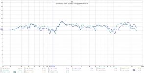
Here they are. All the measurements are made on axis and the and the distance to bonding refers at the distance between the mic and the center area where the cils meet.
This is better isnt it? 🙄
Cheers
Sergiu
This is better isnt it? 🙄
Cheers
Sergiu
Attachments
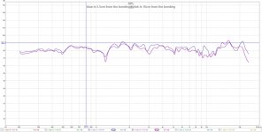
Here they are. All the measurements are made on axis and the and the distance to bonding refers at the distance between the mic and the center area where the cils meet.
This is better isnt it? 🙄
Cheers
Sergiu
they look great dude! almost a straight line !, something i dont get with my mic to be honest 🙁 not sure if it is the mic or the ruba. i personally have no clue what happens. i used some inferior coils if i may say so (etched , and or flex pcb, and alumnium as well), and you used inferior magnets compared to my small ones. the only difference in the magnet department should be SPL
One thing i do know is there is no such thing as a calibration file for all 8000's if proper done they al should be seperated based on serial nr.... 🙁 not one mic is the same especially with cheap chinese products 🙂
Last edited:
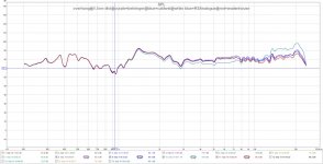
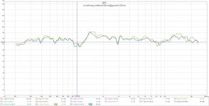
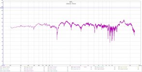
It looks like the behringer is correct; here is a comparison graph between different qualified old studios calibrations and this new beheringer cal (wich i'm using right now). I measured at the same distance of 5.5cm from mic to bonding at the same OVERHUNG 3.4cm coil final version. As you can see the bottom end is pretty much the same and all the magic is from 2.5khz and above... It seems that i was unfortunate to pickup RSAnalogue cal wich seems to be made particularily for a ecm mic that doesnt have that bomb on the high frecv. As we can see all of them, except RSAnalogue are pretty much the same and i looked at the graph and i have differences between 2~4.5dB at the top end wich is decent. I strongly think that i may not be able to make an accurate distortion graph or SPL graph because i dont have an anechoic room (and the mic is picking up some noise++i'm measuring the speaker with a nontreated wall at 40cm dist from the speaker) but with the behringer and West Caldwel Labs calibrations i can definetly know where i am (with a pretty small error) with the frecv responce.
And the SPL may not be a problem at all because i will measure the SPL from the 15" PA speaker first and then the ruban to make the final filters, so neither problems here .
Bellow is the graph with the measurements from 4 different producers/studios and the calibration files that i used to compare them and to know where i am i compressed the other three (RSAnalogue, Wadenhome Sound, Caldwel Labs) because i couldnt upload them because of the .cal termination. If there is problem downloading them please pm me.
As you can see the problem with this ruban is where i pointed out at about 950hz where i have that dip. I think i didnt perceive that so well because i read somewhere on the web that the human ears are less sensitive there but very sensitive betwen 1.3~1.8khz where i strangelly have that peak... This seems to be a poor contact fr shure or a resonance there.
Cheers
Sergiu
Attachments
Last edited:
they look great dude! almost a straight line !, something i dont get with my mic to be honest 🙁 not sure if it is the mic or the ruba. i personally have no clue what happens. i used some inferior coils if i may say so (etched , and or flex pcb, and alumnium as well), and you used inferior magnets compared to my small ones. the only difference in the magnet department should be SPL
One thing i do know is there is no such thing as a calibration file for all 8000's if proper done they al should be seperated based on serial nr.... 🙁 not one mic is the same especially with cheap chinese products 🙂
I this it has to be something in th coils and the contact my friend..
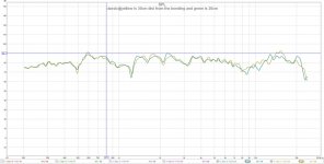
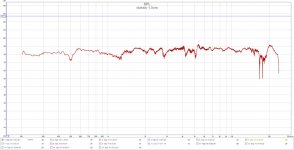
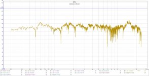
Here are the graphs from my Overhung 3.4cm coil version. I have chosen to work with the Behringer cal from now on (it seems pretty reasonable to me).
Attachments
"So basically all my old measurements graphs till now still remains good and valid if you add a +5dB from 2khz to 7khz and a rough -10db from 15khz to 24 khz. The real problem was only at the high registry where i had that peak... I'm not taking into account the 5dB lower sensitiviti from 2 to 7 khz because the graph remains the same there, only fewer dB wich is not such a big problem..."
I want to correct my statement from an earlyer post (copied here, above):
My old measurements graphs till now still remains good and valid if you add a +5dB from 2khz to 10khz and a rough -8db from 15khz to 24 khz.
I want to correct my statement from an earlyer post (copied here, above):
My old measurements graphs till now still remains good and valid if you add a +5dB from 2khz to 10khz and a rough -8db from 15khz to 24 khz.
Bit i Dont get it , Looks good is Not the best way to Recife to use a calibratiln file... I can Taylor the file to smooth everything out hoe do you know what is the mic and what is the ruba ?
Bit i Dont get it , Looks good is Not the best way to Recife to use a calibratiln file... I can Taylor the file to smooth everything out hoe do you know what is the mic and what is the ruba ?
Hello my friend,
I didnt quite get what you where saying.
And what do you mean how do i know what is the mic and what is the ruba?
Bit i Dont get it , Looks good is Not the best way to Recife to use a calibratiln file... I can Taylor the file to smooth everything out hoe do you know what is the mic and what is the ruba ?
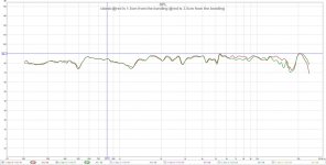
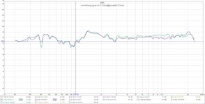
Dont get too impressed by the graphs, they are smooth because i use 1/24 smoothing from the program. But if you look at the graphs bellow, wich are non smoothed now, you will see that if i increase the distance from the mic to ruban, the graph becomes pretty messi (exactly as it was before) as you can see bellow.
I made my meaurements after i spoked with a friend of mine wich is winding and refurbishing speakers, and he told me that if i dont have an anechoic chamber i should measure the rubans from very close distance (about 2cm from the bonding) because the mic is omnidirectionall and could pick up allot of reflections and ground noise.
After speaking to him i readed a tutorial on the web of how do i have to measure a speaker, to confirm this aspect, and what do you know, it seems that the mic was really picking up reflections and ground noise from my listening room as the distance from the membrane bonding increased.. Look bellow ,i posted the "classic" ruban measurements again with no smoothing and increased distance.
Attachments
So with one row flipped it makes more sense:


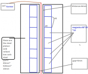
Hello Solhaga,
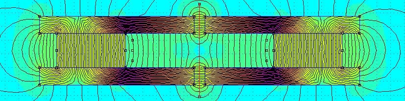
Can you please simulate this for me? I atached a drawing bellow?
I tryied but still didnt understand how femm works.
I need a litle help here. The ideea is that i need some extra dB for my ruban and i have to modify the structure a bit. My magnets are now 1cm away from the edge of the steel plates and i have a 3 mm gap and i want to get them closer at 6 mm but with a 4 mm gap. Would this be possible? Will it saturate the steel?
Can you simulate my curent magnet structure in plus please so that i can see where i am now with my curent config (my magnets are 1cm away from the edge of the steel plates and i have a 3 mm gap, and the rest is the same as in the pic bellow).
Thanks
Sergiu
Attachments

Haha sorry serg, my phone was on Dutch it screwed everything 🙂 I ment we can't say the curve of the cal file should be like this. So the result might look good. But we just don't know. Maybe we are compensating the problems of the ruba instead of the mic. We just don't know🙁 do you know anyone with a serial based calibrated umik near you ? So you can get a better cal file , I know it's still not the best mic
Hello my friend,
No prob my friend. It seems that the umik its pretty much rare here in my town... Maybe the uncalibration of my mic preamp was not only generating a huuuge amount of distortion but was also generating like a saw of spikes. We should have figured out from the first time that my spikes where abnormal but i didnt knew. The situation was like the membrane was resonating on each frecv and bouncing incontrolabily. Please corect my comparison if i'm right: the measurements where showing that the membrane of the ruban was moving like everywhere, more like an unsufficient tensioned electrostat membrane.
I think you are right, maybe we tried to corect something that was only in the mics, because as you have seen in unsmoothed frecv graph that as the distance increases more than 5.5cm from the bonding, the graph strats to go wild with peaks and dips (and seems to transform in a saw like graph...)wich is pretty normal because my room is untreated at all.
Can you please measure your ruban from 2,5 cm dist from the bonding? I am pretty curious.
Cheers
Sergiu
I guess that the magnets have the flux through the largest surface?Can someone help me with a simulation for the pic from bellow. I want to get the magnets closer to improve sensitivity.
FEMM cannot simulate according to your layout as it would require 3D simulation, The drawing should be made as an inter section seen from the top (or bottom).
A glance at your drawing tells me that there are no magnetic circuit with gaps.
What are you trying to accomplish (I haven't read the whole thread)?
Anyway, I'll try to simulate it in a day or two.
(PM me if you want my attention, I'm not that active when it comes to DIY Audio right now. I've been too busy building on my big di-pool the last year or so)

Last edited:
Hi Solhaga,
No problems. I'll redraw the magnetic circuit again.
Nice pool you have there.
Thanks
Sergiu
No problems. I'll redraw the magnetic circuit again.
Nice pool you have there.
Thanks
Sergiu
This is at 5,5cm but if i get closer at 2,5 cm the graph smooths even further...
If you go past thecylinder front the phase issue Goes up in frequency
- Home
- Loudspeakers
- Planars & Exotics
- A DIY Ribbon Speaker of a different Kind