Also folgendes. Die Schwingspule, der Schwingspulenbildner und die Zentrierspinne sollten das gleiche Gewicht wie die Membran haben.
Sie sehen, wie ich eine zentrierende Spinne gemacht habe, die nicht die gesamte Länge haben muss? Die gelben Teile.
Unfortunately, I made another mistake.
The centering spider is not included in the weight calculation of the drive. this must be counted as membrane weight!
servus
Sie sehen, wie ich eine zentrierende Spinne gemacht habe, die nicht die gesamte Länge haben muss? Die gelben Teile.
Unfortunately, I made another mistake.
The centering spider is not included in the weight calculation of the drive. this must be counted as membrane weight!
servus
[/ATTACH]
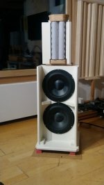
Now my speaker is ready.
There may still be little things to improve in the future.
The timbres are the same as with my Manger MSW.
The Manger MSW has a little more speed at high frequencies and is therefore a little more pleasant to listen to.
The rubanoid has a lot more power and I don't have to worry about overload. The spatial mapping is also better with the Rubanoid, as I built it, with only two semicircles.
I am mentioning the side damping again. (Monacor MDM 20) This is necessary because otherwise the structure-borne sound is reflected back and forth on the membrane. Although this results in more decibels, the sound is fuzzy.
With Audio nec and the Swiss Rubanoid, I can't see exactly whether they are damping. If not, the stuff is no good either. Audio nec can be heard on YouTube. Very treble-heavy and the voices are too transparent. Voices should have a full sound if the recording allows it, of course. I am aware that youtube recordings do not allow any real judgment.
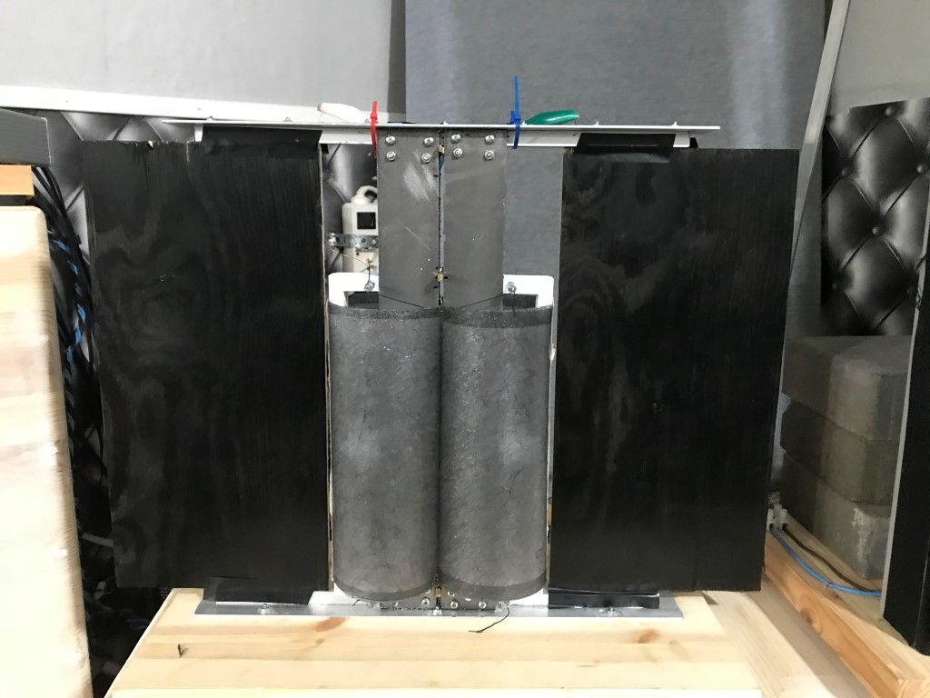
I briefly summarize the data, my construction.
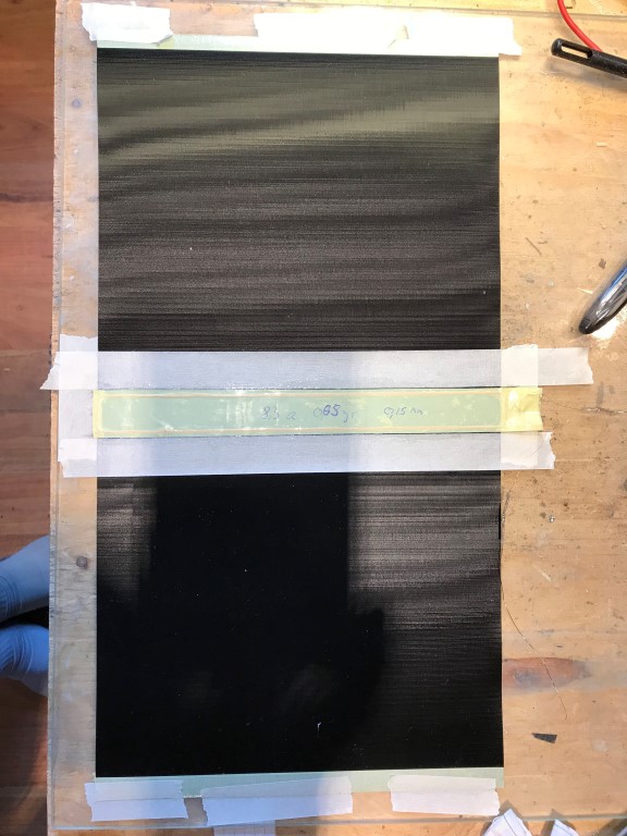
Membrane made of 120 grams / sqm with painting. First page: varnish layer with a lot of varnish to soak the whole paper. Second side with little paint and then again the first side with paint spray, so only very little paint. Always wait for the drying time for the next layers.
Test results after 4 days at the earliest.
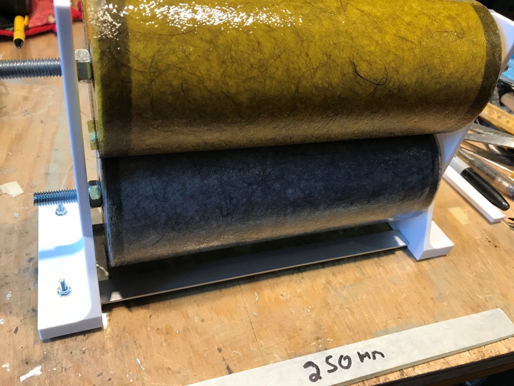
Dimension: 28cm x 15cm, 3cm of which is glued for the voice coil holder.
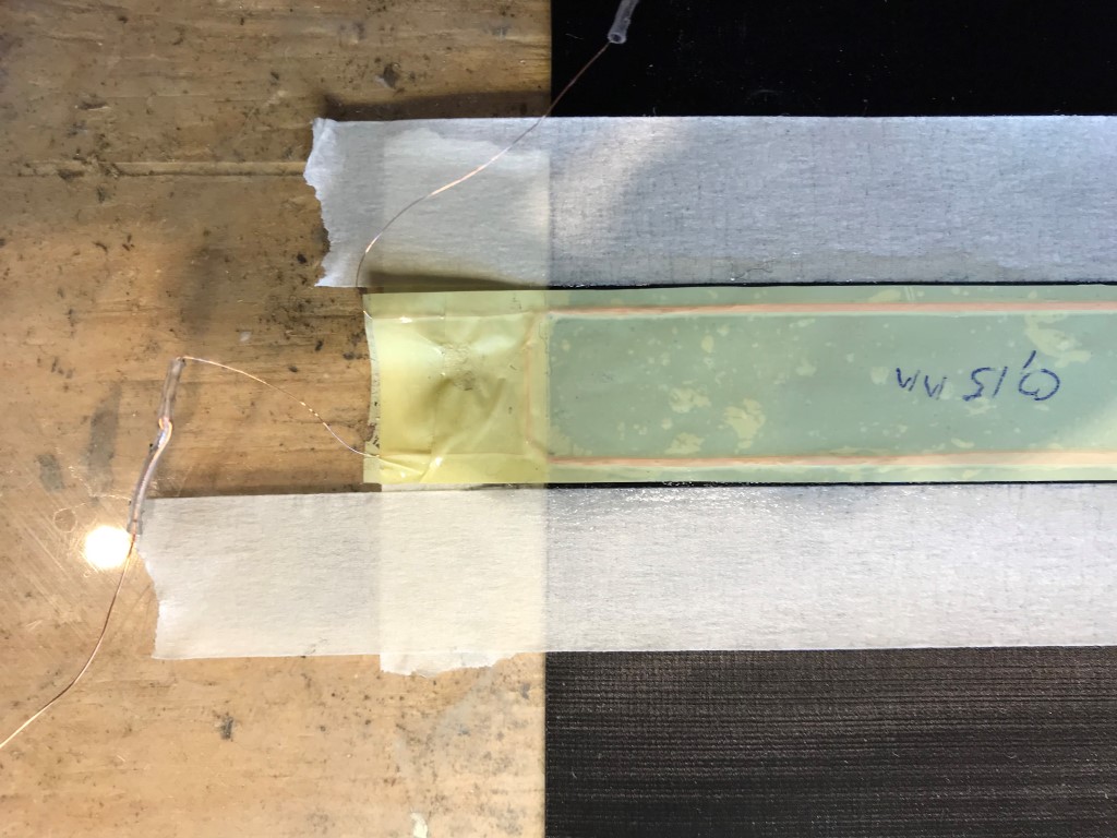
Two coils with 16 turns each with enamelled copper wire 0.2mm diameter.
Slight overhang
Underhang
Underhang
Slight overhang
See photo
Theoretically about 22 to 24 Tesla meters
For me the easiest way to make it with 2K glue, with 90 minutes slowly solid. Very hard.
First apply the glue, then wrap the turns around the fiberglass reinforcement, which is used as the core. Time required: 15 minutes to apply the glue and 30 minutes to wrap. Wait until the glue is a little stronger, then you can push something. Not an easy job.
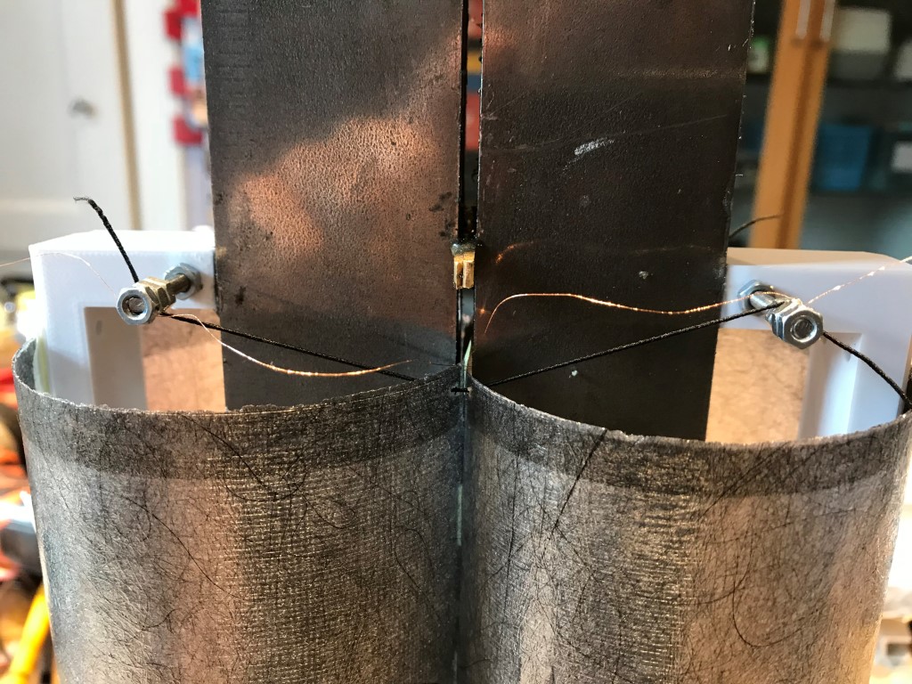
Magnets 5 x 20mm x 20mm. Iron 28cm x 20mm x 6mm.
Gap about 2.6mm. Of which 0.2mm copper foil to better reach the high frequencies.
In my opinion it is very difficult to get a good result if you don't know the bending wave speakers very well. They all have the same timbres, like göbel and manger msw ......
Kind regards
Now my speaker is ready.
There may still be little things to improve in the future.
The timbres are the same as with my Manger MSW.
The Manger MSW has a little more speed at high frequencies and is therefore a little more pleasant to listen to.
The rubanoid has a lot more power and I don't have to worry about overload. The spatial mapping is also better with the Rubanoid, as I built it, with only two semicircles.
I am mentioning the side damping again. (Monacor MDM 20) This is necessary because otherwise the structure-borne sound is reflected back and forth on the membrane. Although this results in more decibels, the sound is fuzzy.
With Audio nec and the Swiss Rubanoid, I can't see exactly whether they are damping. If not, the stuff is no good either. Audio nec can be heard on YouTube. Very treble-heavy and the voices are too transparent. Voices should have a full sound if the recording allows it, of course. I am aware that youtube recordings do not allow any real judgment.
I briefly summarize the data, my construction.
Membrane made of 120 grams / sqm with painting. First page: varnish layer with a lot of varnish to soak the whole paper. Second side with little paint and then again the first side with paint spray, so only very little paint. Always wait for the drying time for the next layers.
Test results after 4 days at the earliest.
Dimension: 28cm x 15cm, 3cm of which is glued for the voice coil holder.
Two coils with 16 turns each with enamelled copper wire 0.2mm diameter.
Slight overhang
Underhang
Underhang
Slight overhang
See photo
Theoretically about 22 to 24 Tesla meters
For me the easiest way to make it with 2K glue, with 90 minutes slowly solid. Very hard.
First apply the glue, then wrap the turns around the fiberglass reinforcement, which is used as the core. Time required: 15 minutes to apply the glue and 30 minutes to wrap. Wait until the glue is a little stronger, then you can push something. Not an easy job.
Magnets 5 x 20mm x 20mm. Iron 28cm x 20mm x 6mm.
Gap about 2.6mm. Of which 0.2mm copper foil to better reach the high frequencies.
In my opinion it is very difficult to get a good result if you don't know the bending wave speakers very well. They all have the same timbres, like göbel and manger msw ......
Kind regards
Attachments
[/ATTACH]
Now my speaker is ready.
There may still be little things to improve in the future.
The timbres are the same as with my Manger MSW.
The Manger MSW has a little more speed at high frequencies and is therefore a little more pleasant to listen to.
The rubanoid has a lot more power and I don't have to worry about overload. The spatial mapping is also better with the Rubanoid, as I built it, with only two semicircles.
I am mentioning the side damping again. (Monacor MDM 20) This is necessary because otherwise the structure-borne sound is reflected back and forth on the membrane. Although this results in more decibels, the sound is fuzzy.
With Audio nec and the Swiss Rubanoid, I can't see exactly whether they are damping. If not, the stuff is no good either. Audio nec can be heard on YouTube. Very treble-heavy and the voices are too transparent. Voices should have a full sound if the recording allows it, of course. I am aware that youtube recordings do not allow any real judgment.
I briefly summarize the data, my construction.
Membrane made of 120 grams / sqm with painting. First page: varnish layer with a lot of varnish to soak the whole paper. Second side with little paint and then again the first side with paint spray, so only very little paint. Always wait for the drying time for the next layers.
Test results after 4 days at the earliest.
Dimension: 28cm x 15cm, 3cm of which is glued for the voice coil holder.
Two coils with 16 turns each with enamelled copper wire 0.2mm diameter.
Slight overhang
Underhang
Underhang
Slight overhang
See photo
Theoretically about 22 to 24 Tesla meters
For me the easiest way to make it with 2K glue, with 90 minutes slowly solid. Very hard.
First apply the glue, then wrap the turns around the fiberglass reinforcement, which is used as the core. Time required: 15 minutes to apply the glue and 30 minutes to wrap. Wait until the glue is a little stronger, then you can push something. Not an easy job.
Magnets 5 x 20mm x 20mm. Iron 28cm x 20mm x 6mm.
Gap about 2.6mm. Of which 0.2mm copper foil to better reach the high frequencies.
In my opinion it is very difficult to get a good result if you don't know the bending wave speakers very well. They all have the same timbres, like göbel and manger msw ......
Kind regards
nice good job ! any measurements ?
Hello
Unfortunately I have to use a three way system. I would prefer a 2 away.
Why it is like that. My listening room is very unusual, even with a very short reverberation time. Approximately 0.32 seconds, with 94 cubic meters of room volume.
A woofer with a diameter of 30 cm already reaches its limits at 76 dB.
I separate the Ruba at 340 Hz, Linkwitz 4 order and the bass-midrange at 97 Hz, Linkwitz 8 order. Right all the time, as best as possible. (delay)
For measured values I only have a handheld measuring device and CD test tones (HIFISH)
It does not seem to reach 20 kHz.
The Manger MSW runs up to 30 kHz, but even this does not reach 20 kHz on my measuring device. Anyone who is familiar with measurements should also know that such measurements can only be carried out under certain conditions. Even if a gating measurement process takes place.
Something else about the frequency response. Why is it worth striving for 20 kHz that most people don't hear?
Quite simply, there are also the difference tones. This means that if a 20 kHz tone sounds at the same time as a 10 kHz tone, this results in a 15 kHz tone.
Then there are also noises in addition to the tones .........
regards
Totally forgot; behind the membrane I have attached an acoustic lens, a scatter lens. That makes the sound more precise and an improved spatiality, with a wider sweet spot.
Hello,
I know magnets are used in big and small speakers. In the past there were used ferrite ring magnets that were heavy and large. Is now with neodymium magnets a miniaturisation realised? What about quality of sound... is it improved with neodymium magnets compared to old heavy ferrite magnets?
Regards,
Cristian
Hello
Nedym magnets give a higher flux density, thus a stronger drive. That they are smaller is a practical positive effect.
The question of magnets is not particularly important. other components have much more influence on the sound. for example the centering spider.
Greeting
Nedym magnets give a higher flux density, thus a stronger drive. That they are smaller is a practical positive effect.
The question of magnets is not particularly important. other components have much more influence on the sound. for example the centering spider.
Greeting
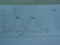
Kammfilter effekt
View attachment 910781
The Rubanoid is now on an open baffle. Unfortunately, the Rubanoid has a fundamental problem and that is the comb filter effect. The two diaphragm semicircles are like two tweeters next to each other. This leads to problems in the treble, this can be shown with the program Edge, baffle step. The frequency response drops early, unless the microphone is exactly in the middle of the membrane
When listening to music, female voices produce sound artifacts from both sides of the speakers. That doesn't sound clean, but a bit harsh.
Now I've started an experiment. As you can see on the photo, a membrane is now covered and the sound is directed to the side. You have to get used to it because the music sounds a bit unspectacular, but a lot cleaner. I am not yet able to make a final judgment. The cover must be positioned very precisely. Interesting that measured 20kHz is a few dB louder!
The tweeters from Audio Nec and the Swiss Rubanoid, in my opinion, are used because of the comb filter effect and not because the Rubanoid could not reach 20 kHz.
regards
Attachments

Hello,
I have found an interesting variant :
Voxline - Premieres notes de la version en bronze du...
What seems to be different is the open sides.
Indeed this is something we have not been exploring, but in their pitch they says that opening the sides is something that really boosted the quality of the sound.
I remember from reading all this thread that some of you have been fighting to absorb the sound and reflexion inside the tube created by the way it was build.
Maybe opening the sides as they say is a good solution.
Their motor does not look as strong as the ones here.
Maker : voxline
model : vertex eidolon
Not a lot of informations available, their debut seems difficult
And to make bass with a janus : the infraflex
infraflex – Recherche Google
Gonna try one of these in the future.
The creator is very kind and gives building plan on demand.
But he isfrench so everything can be found...but in French
infraflex – Recherche Google
Gonna try one of these in the future.
The creator is very kind and gives building plan on demand.
But he isfrench so everything can be found...but in French
finally, it looks like they closed they closed the sides on the newest version that can be seen here
VOXLINE - Unbox your audio experience
VOXLINE - Unbox your audio experience
Great video, thanks for posting. It is not evident whether circular segments are used on both sides.
My Rubanoid only has a membrane on the front and a divergent lens on the back. It is especially important to reduce the comb filter at the front, but also to do something at the back.
In the spring I will build a Rubanoid with only a semicircle membrane. The efficiency will probably be a lot lower, but the comb filter is significantly less. the 20kHz should also be reached earlier due to the lighter construction
regards
Please correct me if I am wrong, but is everyone using an etched aluminium or copper as their voice coils? I presume this is the case as there doesn’t seem to be a easy way of winding “say” 0.1mm enamelled wire into a flat slot shape.
Joppe - I know you etch, but have you ever used wire?
Joppe - I know you etch, but have you ever used wire?
I used wire in my attempts:
Eight turns of 0.1 mm enamelled wire resulted in 8.3 ohm.
The finished coil was 0.15 mm thick and weight was 0.65 grams.
Dimensions were 15 mm times 200 mm.
Here I glue it to the membrane:
In the motor:
First tests, a little problem with the wires touching the motor:
Solhaga?s first attempt to bend waves. - YouTube
I later gave up due to problems with the membrane's fastening at the ends.
Or maybe not... - YouTube
An externally hosted image should be here but it was not working when we last tested it.
Eight turns of 0.1 mm enamelled wire resulted in 8.3 ohm.
The finished coil was 0.15 mm thick and weight was 0.65 grams.
Dimensions were 15 mm times 200 mm.
Here I glue it to the membrane:
An externally hosted image should be here but it was not working when we last tested it.
In the motor:
An externally hosted image should be here but it was not working when we last tested it.
First tests, a little problem with the wires touching the motor:
Solhaga?s first attempt to bend waves. - YouTube
I later gave up due to problems with the membrane's fastening at the ends.
Or maybe not... - YouTube
Cheers for the reply Solhaga,
I've been interested in how to wind a wire coil and have been following the work done by Russ Gries, who converted a 3d printer and added a “drag knife” to lay the wire. However after my own experiments with 0.1mm wire I experienced a few issues with the turns overlapping and becoming thicker than planned.
This brings me to asking what technique your using to wind your wire?
I wired it around a couple of pins on a foam board.
This was my first attempt with 0.20 mm wire, I don't remember how many turns:
I later embedded coils in the resin when making carbon fiber membranes:
(The membrane in the post above is 3D printed)
Hung up the membrane and connected the coil:
This was my first attempt with 0.20 mm wire, I don't remember how many turns:
An externally hosted image should be here but it was not working when we last tested it.
An externally hosted image should be here but it was not working when we last tested it.
An externally hosted image should be here but it was not working when we last tested it.
An externally hosted image should be here but it was not working when we last tested it.
I later embedded coils in the resin when making carbon fiber membranes:
(The membrane in the post above is 3D printed)
An externally hosted image should be here but it was not working when we last tested it.
An externally hosted image should be here but it was not working when we last tested it.
Hung up the membrane and connected the coil:
An externally hosted image should be here but it was not working when we last tested it.
An externally hosted image should be here but it was not working when we last tested it.
Last edited:
Cheers for sharing. This was how I started doing it. It's amazing how such a simple shape is so difficult to produce.
Spule - Google Photos
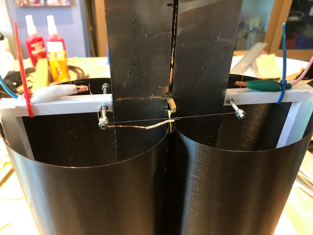
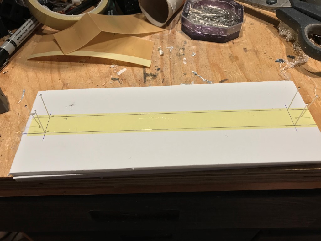
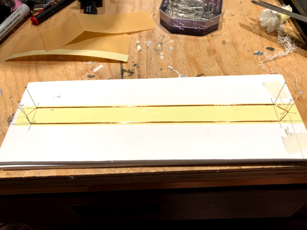
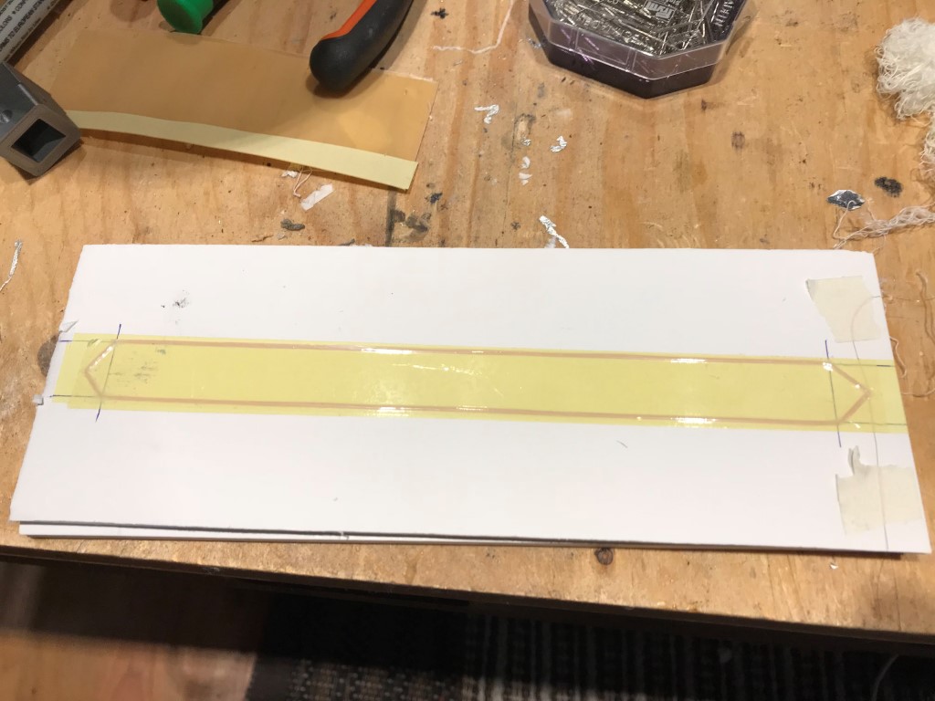
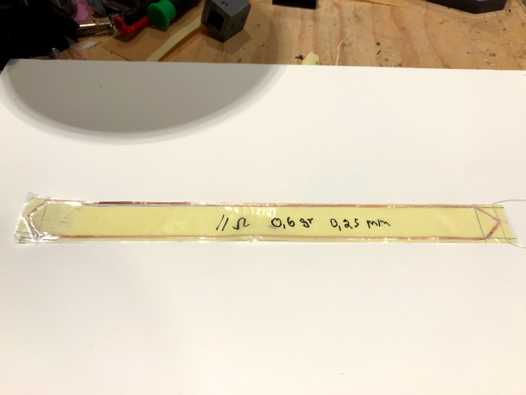
My way of winding the coil.
1. Glue the fiberglass core onto the paper.
2. add 2 components of glue around the fiberglass core. Strength only after 1.5 hours.
3. Clamp the piece of wood over fiberglass. the notches in the wood are used to push the copper wire onto the fiberglass with a toothpick.
4. Both membrane halves have a coil.
The voice coil is getting a little heavy. with the next generation i will only use the fiber optic core without paper. I will then glue the membrane to the outer end of the spool.
Last edited:
- Home
- Loudspeakers
- Planars & Exotics
- A DIY Ribbon Speaker of a different Kind