Not fearing my bad French language skills any longer, I poked around that entire site. There is a complete parts list and several more pictures.
His horseshoe cheat is even better than mine: one magnet and two pieces of steel per side (duh!).
Polyfill stuffing looks like it is handling the HF of the backwave, and the LF backwave can likely be ignored, since it will just be constructive to the radiating surface on the other side of the transducer.
There also appears to be some cotton-covered elastic bands in the bill of materials. I am guessing these are for holding the white fluffy away from the diaphragm, or possibly for applying a restoring force to keep the coil in the gaps.
OK, who can read the French on this page:
http://home.tele2.fr/mon-site-perso/JANUS50_approvisionnement.htm and then tell us what the membrane is made of? (or is he the source for the "special paper" and we have no idea what it is?)
Has anyone ever heard one of these? Can they really get down to 100 or 200Hz?
ANY sort of guess on how much moving mass is involved in total?
And any idea why the Rubanoide version is split into 2 driver sections? This would otherwise seem like a good design to keep to a single, full length driver.
His horseshoe cheat is even better than mine: one magnet and two pieces of steel per side (duh!).
Polyfill stuffing looks like it is handling the HF of the backwave, and the LF backwave can likely be ignored, since it will just be constructive to the radiating surface on the other side of the transducer.
An externally hosted image should be here but it was not working when we last tested it.
There also appears to be some cotton-covered elastic bands in the bill of materials. I am guessing these are for holding the white fluffy away from the diaphragm, or possibly for applying a restoring force to keep the coil in the gaps.
OK, who can read the French on this page:
http://home.tele2.fr/mon-site-perso/JANUS50_approvisionnement.htm and then tell us what the membrane is made of? (or is he the source for the "special paper" and we have no idea what it is?)
Has anyone ever heard one of these? Can they really get down to 100 or 200Hz?
ANY sort of guess on how much moving mass is involved in total?
And any idea why the Rubanoide version is split into 2 driver sections? This would otherwise seem like a good design to keep to a single, full length driver.
it really only says :
papier spécial 175 gr
special paper 175gr
not much to it
it does look like regular "contruction" paper
we use in canada at kindegarden and first years of schooling ...
i find this design intriguing,
wonder how that could be used for a floor to ceiling
line "array" with some woofers
again we do not have any measurements on distortions and other factors..
neededandwanted said:
His horseshoe cheat is even better than mine: one magnet and two pieces of steel per side (duh!).
There also appears to be some cotton-covered elastic bands in the bill of materials. I am guessing these are for holding the white fluffy away from the diaphragm, or possibly for applying a restoring force to keep the coil in the gaps.
And any idea why the Rubanoide version is split into 2 driver sections? This would otherwise seem like a good design to keep to a single, full length driver.
A longer/higher build might cause ressonance and contol issues
Havent noticed the elastic bands
But makes sense
They are fore a well damped suspended control of "diaphragm, much like a spider o an ordinary driver
And magnet system does seem more simple than I had planned to do it
Man, those magnets could be exstremely powerful
Maybe also consider whether it should be underhung or overhung "coil" design
And how much does thing actually move
Also consider whether to use thin enamel wire, or plain alufoil
I reckon the "coil" wire/foil should be in between the two diaphragm halfs, glued in when assemling the diaphragm
This way they are positioned exactly in the middle of fieldgap
Good spotting of these details 😎
Looking at magnet system I may see a small issue
I see some risk to also have a field across, from gap to gap
That could cause the diaphragm/"coil" to move from side to side
Maybe a simulation would reveal this 🙄
edit, strange 😕 all the metal in the picture looks more like aluminium
Attachments
tinitus said:Haven't noticed the elastic bands But makes sense
They are for a well damped suspended control of "diaphragm, much like a spider on an ordinary driver
That makes sense, but seems like a sort of sloppy way to keep the coil centered in the gap. If the elastic can stretch enough to allow the voice coil to move in the correct direction without a lot of resistance, it seems that it wouldn't control the sideways motion well.
They claim a 1.6 Tesla flux on one page and 1.8T on another. I think this gets pretty close to the maximum flux that can be "conducted" through iron. (anyone up to speed on the permeability limits?)And magnet system does seem more simple than I had planned to do it. Man, those magnets could be extremely powerful.
Having a really small gap buys us a lot of force, compared to typical ribbon gaps of 0.75 inches.
Well, I haven't seen real specs on efficiency or sensitivity. The claim is for 200-20,000Hz, but with no expressed "plus or minus 3dB" or anything I can find. Who knows? Maybe it is 40dB down at 100Hz.Maybe also consider whether it should be underhung or overhung "coil" design. And how much does thing actually move?
I also see a claim of sensitivity "102 dB" without the standard @1W 1 meter, so it may be 102dB at 80 watts for 2kHz, measured 1cm from the driver. (I swear I saw a sensitivity of 85dB expressed for this on one of the pages, though)
So, no idea how much this moves, because I can't work backwards from how much AIR it needs to move to achieve the published specs. 102dB at 20kHz can be done with very little excursion.
Except for the extra mass of voice coil windings, this may work well in a severely overhung fashion - just keeping a fixed number of windings in the gap at all times. I would also start by experimenting in that direction because extra wire traces are much cheaper than wider magnets.
The write up says that the voice coil is made of epoxy with etched traces (like a circuit board) I believe. Likely, the diaphragm material starts at the ends of the "voice coil" and is just glued in place.Also consider whether to use thin enamel wire, or plain alufoil. I reckon the "coil" wire/foil should be in between the two diaphragm halves, glued in when assemling the diaphragm
This way they are positioned exactly in the middle of fieldgap
Using a thin foil is going in the wrong direction, I think. Regular voice coils are often "edgewound" using flat wire turned the other way - so it stacks like a laminate. In a ribbon, you want to maximize driven surface area, so try to capture force across the entire gap. Here, we want skinny wires and lots of them.
This also allows us to look at a transformerless design as it should be possible to get a DC resistance, and impedance up into a range where it can be driven directly. (I think the documentation is claiming 4 Ohms and "purely resistive" so that is likely a long wire.)
I am guessing that the small gap vs. big gap problem would be a non-issue for a few reasons:Looking at magnet system I may see a small issue
I see some risk to also have a field across, from gap to gap
That could cause the diaphragm/"coil" to move from side to side
Maybe a simulation would reveal this 🙄
-- the small gap (where we WANT the flux) is so much smaller than the "short circuit" gap where flux would be wasted, that the circuit will go much more thru the small gap. This IS a real design consideration though. We need the front gap and rear gaps to be separated by some distance.
-- any leak across the large gap will happen not just at the ends of the iron, but all along then length of them
-- the resulting force on the voice coil from the large gap, will be balanced by an opposite force from the other magnet assembly on the other side.
This definitely needs to be FEMM'ed up to see the exact effects. Remember, the wire with current wants to cut across lines of flux, not go parallel to them. In FEMM, it will be easy to visualize if this is going to be a problem as we will see the lines generated from all 4 poles. (and good catch, since I think we all got a refresher on the right hand rule yesterday...)
All of it should be aluminum, except for the 4 pole pieces. But, yes. They also look incredibly like aluminum......all the metal in the picture looks more like aluminium
dipole vs. bipole on this one?
This page: http://www.6moons.com/industryfeatures/rubanoide/rubanoide.html
...really goes way out of its way to assert that the design is bipolar, not dipolar.
And it really goes out of its way to demonstrate that they know what those two words mean (compared to many documents that accidentally say "bipole" when they are referring to a dipole).
For example:
"The Rubanoïde works as a bipole unlike Magnepans, Apogees and most electrostatics."
and:
"As a bipole, it stages more naturally than pinpoint monopoles. It also avoids dipole cancellations."
This page also makes some hard-to-believe claims for this loudspeaker:
"Features include 103dB efficiency from 200Hz to 20,000Hz"
and:
"The efficiency in energy transfer from the membrane to the air is such that even for higher frequencies, the sound is more realistic and dynamic than for example a Raven R3 ribbon. This is particularly interesting as the Raven features a 30mgr moving mass while the Rubanoïde has a 30gr moving mass."
In all fairness, those type of claims would need to be in place for me to shell out the type of money these are selling for. The complete system on this page looks like it cost a bit more than something the rest of us might buy to raise a family in.
But back to the "bipole" claim. I can't see how it could be a bipolar transducer from the pictures I have seen so far. All design considerations aside, I would prefer a bipolar radiation pattern, but it is really hard to produce efficiently.
AND combining this with the claims elsewhere that the radiation pattern is nearly 180 degrees - does this thing claim to be omnidirectional?
Is it possible that the "Rubanoïde" variant is truly bipolar, while the original Janus50 was a dipole?
Also worth reading that page is the apparent challenge: he pretty much dares us to attempt to emulate his design. For 15,000 Euro for a pair, I think it is a worthy thing to try.
Let's see, magnets, iron or steel, aluminum. For the membrane paper, I think it would sound best if we used uncut sheets of 100 dollar bills...
Re: dipole vs. bipole on this one?
Me neither
I would say more like a push-pull dipole 😀
You are also right that several construction details seems to need further attention
Still thinking about magnet/iron design
Depending on how its done, it could be EXSTREMELY difficult and dangerous to assemble
neededandwanted said:
But back to the "bipole" claim.
I can't see how it could be a bipolar transducer from the pictures I have seen so far.
Me neither
I would say more like a push-pull dipole 😀
You are also right that several construction details seems to need further attention
Still thinking about magnet/iron design
Depending on how its done, it could be EXSTREMELY difficult and dangerous to assemble
Might also be worth to consider which typ of strong magnet that are commonly available, at affordable prices
I also find it important to use a construction principle that on its own will give a sturdy and accurate result
And as simple as possible, without too much fiddling
With the below pictured design I am worried about whether the magnets prefer to stick to the iron, or whether the magnets would like to get together 😱
Attachments
It could be a true bipole.If the "voicecoils" are separated so that they move in opposite direktions,out of fase, and held in possition With rubberband or likely.
I was thinking that my planar could performe better in the deep end ,if i mounted simmilar "horns" as the rumanoide. If so ,i have an idea how to make it look better.
I was thinking that my planar could performe better in the deep end ,if i mounted simmilar "horns" as the rumanoide. If so ,i have an idea how to make it look better.
Here is a FEMM sim.Iron 10x40mm. Neodymn. n40. 10x30mm.Fieldgab 2,5 mm. field strength 1,35T. Flux in iron 1,8T.I think it shuld not exeed 2 T.

Here is one using 10x50mm. Iron ,and 10x50mm.Neo 40.fieldstrength 1.8T.-1.9T. !!Flux in Iron 1.9 T.
Voicecoils could be made of 1mm.pbc. dual layer etched coils.

Voicecoils could be made of 1mm.pbc. dual layer etched coils.
http://en.wikipedia.org/wiki/Saturation_(magnetic)
"Different materials have different saturation levels. For example, high permeability iron alloys used in transformers reach magnetic saturation at 1.6 - 2.2 teslas (T), whereas ferrites saturate at 0.2 - 0.5 T."
The gap can be made longer, and made deeper, and skinnier for more force, but I don't think we are going to be able to push it any higher than about 1.2-1.6T using steel pole pieces.
Since these pole pieces may also need to act as the physical supports for a lot of magnets, using a soft type of iron will likely not be able to maintain the gap evenly, if only supported at the top and bottom.
A design that had supports in the middle somewhere would either need to go through the voice coil "bobbin" in a dipole design, or around the back in a monopole design.
If the front and back are split for a true bipole, the gap can be supported, or even adjusted, at several points, or even continuously. But splitting the front and back gets tricky when looking at the windings.
I wonder if a design very similar to what has been drawn here, but with no rear membrane surface would be practical. We could keep both pairs of magnets, and both the "up" and down" windings, but simply drive the forward element only.
And, actually, this would still be a dipole, but I don't think HF would get radiated well towards the rear.
(changing gears now)
Truth be told, I feel a bit silly pursuing this as a project for at least the following reasons. None of them are show-stoppers, but they are all sitting in the back of my head:
[1] These types of designs have been around and attempted and tested for a long time. But little commercial success has been achieved apparently (with anything other than a small tweeter, and even then, it was a brief success).
[2] We can't seem to find any real published specs. I am sure that "102dB, 200Hz-20kHz" is meant to make us assume certain things, based on how drivers and complete loudspeakers get rated, but I am sure it is hiding some serious data. It is a far cry from getting a complete response curve (polar, or just an on-axis sweep) or T/S parameters.
[3] I would be really happy if it could even cover 800Hz--15kHz, but something in my gut tells me that it won't even have a punchy midrange. (It just SEEMS like that. In the same way that a floor to ceiling true ribbon SEEMS like it wouldn't have any punch - but we know otherwise.)
[4] I have owned 3 different variations of Linny tweeters, and considered them all supertweeters, that merely added sparkle to to the high end -- even when listened to very closely. I am hoping they were just crossed over very high, but one of the loudspeakers (RCA branded, sold by Radio Shack, CAST aluminum enclosure) was a two way design, and I would think they would try and cross as low as possible.
[5] 102dB sensitivity without a horn? Not a lot of similar claims out there.
Depending on your viewpoint, the "too good to be true" claims can be a reason to dismiss the design or at least proceed cautiously, OR to jump right in. OTOH, it would be pretty simple to convert this to a true ribbon as a backup (as long as the gap is adjustable).
I just want to know where are the hidden "gotchas" that have kept such a straightforward design from being more widely built.
båndsei,
I stand corrected. That's a mighty pretty picture.
With real world magnet sizes, how big of a gap can we get at that level of flux? 3mm? More?
Any bright ideas on keeping the voice coil centered in the gap? Putting traces on both side (or in the middle on a non pcb version) will keep the force equal on both sides, and driving it from both the front and rear (using two gaps) should keep it moving in a straight line, but it seems like the smallest breeze in a room, or a bit of sound from another driver would tend to push everything sideways.
LOL - Coat everything with teflon and just let it scrape away occasionally?
Anything mechanical I can think of to keep the VC centered will add lots of mass. The voice coil will also need to be suspended vertically, to keep it from sagging.
I am thinking that were are going to end up with those elastic bands again.
Maybe the pcb could be made of something strongly diamagnetic - that may be strong enough to keep it horizontally centered with such a strong field. It would be repelled by both magnetic poles.
Looking for some Strontium Unobtainium Oxide now...
Båndsei
Very interesting result indeed
Im afraid those magnets will way too difficult and dangerous to handle
Though it might be possible with use of threaded rods, to get the last iron pole in place, but theres exstremely high power on hand here
Commercially assembling would be done before magnetising
Anyway, neos that big cost a small fortune
Thanks for simulating
Any chance you could get time to sim the one below 🙂
But it will probably look very much like what we have looked at earlier
Your sim above clearly shows that things start to happen with the very big neos, but unfortunately not very realistic
But diaphragm weight should be considered, and this one is a bit heavier than a palanar ditto, and is only driven in a small part of its area, where as a planar is active over almost the entire diaphragm, and thereby works ok with much less field strength
Lots of things to consider
I would also expect that an ordinary ribbon supertweet on top of it wouldmake sense
Attachments

tinitus,
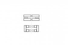
Is that 2 or 3 pieces of steel/iron on each side? If it is 3, and all of the white rectangles with black outlines are iron, then it will short circuit and have almost no flux in the gap.
It it is 2 pieces or iron per side, then it is essentially the same design as the one above it that he made, but stretched vertically.
Also, is there a way I can email or IM you directly? You have disabled the ability for us to email you directly from your profile here.
***********************
BTW, for anyone that has not been following THIS thread:
http://www.diyaudio.com/forums/showthread.php?s=&threadid=137946
... there is a lot over there that we can learn from. They are making a similar design with etched and wound flat voice coils.
Sorry that wasnt clear
Magnets are forming the gap directly
Iron is on the back
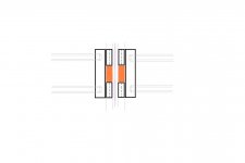
The orange in between the magnets is wood, to keep magnets in place
But magnets are much smaller this way, and its more reasonable to handle
Though I have found some 2" x 2" x 1" N52...45USD...but how to handle those I have no clew, I wouldnt dare to but VERY tempting 😀 maybe it would mean much less magnets 🙄 but people who have handled even much smaller neos know that they behave like crazy when they get close together
edit, ahh, seems I missed the magnets size on Båndseis sims...not quite as big as I thought, and might be worth the hazzle, as with that design the magnets will keep in place, with the iron on both sides
But somehow I think I will prefer a wider gap
Magnets are forming the gap directly
Iron is on the back
The orange in between the magnets is wood, to keep magnets in place
But magnets are much smaller this way, and its more reasonable to handle
Though I have found some 2" x 2" x 1" N52...45USD...but how to handle those I have no clew, I wouldnt dare to
but VERY tempting 😀 maybe it would mean much less magnets 🙄 but people who have handled even much smaller neos know that they behave like crazy when they get close together edit, ahh, seems I missed the magnets size on Båndseis sims...not quite as big as I thought, and might be worth the hazzle, as with that design the magnets will keep in place, with the iron on both sides
But somehow I think I will prefer a wider gap
I have been looking at the parts list for the "rubanoide".So my first simm is made with materials from the list , exept the neos.wich in the list is N35.The gab might be 4mm.in the list there is alu 2x10mm. and it looks like there is 2 of them in the end.I have been looking at an older version ,and from the picture it looks like the voice coil is made of a pcb.The hight.is 51 cm.,so the coil might be 50x510x1.5mm. dual layer pcb.,with two 5x510x1.5mm.pcb, solded to the middle of the "coil"for the strengthning ,sideverts.The magnets might be mounted with a gab,in wich there could be an elastic wire atached to the 5x510x1.5mm pcb.to keep the "coil" centered. This would keep it from moving too much ,as well.
tinitus said:But magnets are much smaller this way, and its more reasonable to handle
Though I have found some 2" x 2" x 1" N52...45USD...
edit, ahh, seems I missed the magnets size on Båndseis sims...not quite as big as I thought, and might be worth the hazzle, as with that design the magnets will keep in place, with the iron on both sides
But somehow I think I will prefer a wider gap
I like smaller magnets as well, if we can get sufficient flux in the gaps.
I still like the steel on the outside, if possible, if for no other reason than to protect the brittle magnets from a flying screwdriver. It would hit the steel instead. I think the best design may be one where the steel is strong enough to hold the gap open.
I don't really know the scale of his drawing, but a bigger distance between the gaps may be necessary, as you mention. That will need to be decided by how the voice coil is wound. I think we are looking at a tall pancake winding that can be largely rectangular, but will need some empty space between the front and back sections (the wires going up and the wires going down).
Ultimately, the design I would like the best would be a tightly stackable one. A design that does not rely on support above and below the magnets, so that many of these could be built individually and then stacked, without any large breaks in the line source. Possibly, a transducer that only has a driven element on the front will be the only easy way to do this.
I don't really care too much what it radiates out the back (bipole/dipole/cabinet mounted) too much. Ideal would be a bipole or something appreaching omni, but I can deal with a dipole easily, or even a strong forward weak backward HF pattern.
I would definitely not prefer to spend $45 USD on each magnet, and seeing the FEMM results from smallish Neo40's, I think it will be possible.
neededandwanted said:
I think we are looking at a tall pancake winding that can be largely rectangular, but will need some empty space between the front and back sections (the wires going up and the wires going down).
Not sure what you mean
But the beauty of such a magnet design is that polarity is reversed, so that no "passive" return wire is needed
This means that the "return" wire fore one gap work as active coil in the other
Quite effective
Im not sure I like the idea of stacked modules at all
I will focus on doing a dedicated widerange midrange module, fore best "focus", and not line a source
Fore good "slam" a good big PRO woofer would be needed anyway
Maybe also consider the music preference of the people at "AudioConsulting"
Im sure they are sophisicated people that only listen to "perfect" recordings, and probably only jazz and classical, and maybe not at very loud levels either
Im quite sure they dont listen to pop and other modern rythmical music...well, I do

The only possible way I know to do that is to releave the mid module of any bass duty
Its a compromise I am willing to take
On the "tall pancake winding" imagine the voice coil looking like a reel of magnetic tape (open reel, reel-to-reel, say, 1/4 inch on a 7 inch reel).
The magnetic tape is flat insulated magnet wire like is commonly used in voicecoils.
The reel would only be 2-3mm wide (as opposed to the magnetic tape reel which is 13mm or more).
Now, take the round, flat tape reel and stretch it to be as tall as the speaker. So, instead of being round, it becomes flat in the front and flat in the back - more rectangular. In the front, a stack of tape goes up, and in the back the stack of tape comes back down -- it is just just the other side of the winding.
Definitely no passive return wires: the windings going up in the front have a magnetic gap to drive them, and the windings going down in the back have their gap. The only wasted coil is the tops and bottoms.
If flat voicecoil wire is used like this, a lot of windings can fit in a very small space and the design could even be underhung, or nearly so.
Using traces on a printed circuit board, we would not be able to pack them as densely, because we still need to etch spaces between the traces. As we start to try packing them more tightly, we also end up with really skinny, high-resistance wires.
The BL of a driver is the product of the density of the magnetic field times the length of the wire in it. The trade off of the extra wire length is the mass of the wire, and when that mass starts to be come large compared to the mass of the diaphragm and the mass of the air we are moving then we will start to have problems. But, for a given length of wire, we are better off packing it as tightly as possible, to keep as much in the gap as possible at all times.
With that reel of flat wire, you can see why the voice coil in the JANUS50 is called a "bobbin."
As far as stacking goes, the Rubanoide is a stack of two elements, but with a big gap in the middle where there is no driven surface. A broken linesource like this will have a comb filter effect for any frequencies with a wavelength smaller than twice the gap size (possibly even 4 times the gap size).
I definitely don't intend to make a woofer out of this. But if a midrange/tweeter of this design is more than a few cm tall, it already is becoming a linesource. I would just like to have the possibility of stacking them, without the gaps. This would involve not having extra pieces that have to go above and below the driven area.
And actually, if they really can play up to 20kHz, they may be a candidate for an alternative for tall true ribbons, and would have essentially the same or lower magnet cost (maybe much lower since we can make a much smaller gap width).
I think the whole VC and former can be very straightforward. I am sure that when it comes to actually making some prototypes where we are really going to need to get wildly creative will be on the surface materials - the diaphragm. It will need to be able to deal with humidity changes, so an untreated paper is likely not feasible.
The speed of wave propagation within the diaphragm material will be a big factor in getting the energy transfered to the air correctly, and the material will likely need to be gradiently more dense going from voice coil to "surround" (or whatever the termination at the sides will be called) so that ALL of the energy is transferred into moving the air, and not making standing waves from reflecting off of the surround.
We want the highest frequencies to be transferred to the air very close to the voice coil (the center of the driven surface) while lower frequencies can be transferred by the full surface area. This avoids have the equivalent of TWO line sources next to each other.
- Home
- Loudspeakers
- Planars & Exotics
- A DIY Ribbon Speaker of a different Kind