I forgot to tel that we know that site and our ruban researched here allready breaks the 20khz by himself and who knows how high it goes (my hardware doesnt measure higher than 23khz)... The only problem is in how flat they go (the one from that site and the one researched here). And this was the 1mil dollars problem hehehe. 🙄
Cheers
Sergiu
Aha

//
Aha
//
That's a short answer 🙂 I doubt any Clame on the rubbanoide is valid. At least when listening slightly of axis all goes weird 🙂
I did not encounter any predicted response at least in my measurements , from good to terible peaks and nulls without even changing anything except measuring conditions. I think audio nec is not going to publish any measurement soon same goes for the original rubsnoide , the Francois version but mainly the overpriced audio consulting. They are not going to publish anything as is protocol for most "high end audio"
Hello my friend,
I wrote my answers in your post.
That's a short answer 🙂 I doubt any Clame on the rubbanoide is valid.
Hell yeah you're right! Flat impedance, linear frecv resp... Thats all c**p!
Allmost all fullrangers (even if they sound very good and cost allot of money) have here or there a peak or a dip of almost +-8dB (see some good examples as fountek, feastrex etc), and this is inevitable and the producers should'nt tell lies or dont post measurements.
At least when listening slightly of axis all goes weird 🙂
I forgot to tell you about something i discovered on my stacked rubas (the two small 23cm height stacked on the same structure here http://www.diyaudio.com/forums/plan...on-speaker-different-kind-87.html#post4807592). The thing that i discovered is that when the rubans got smaller they had more dips between 600hz and 2.5khz (compared to one or two small dips at 1.1khz in the 50 cm ruban) wich where very noticeable (perceived as a lack of mids and increase in hights) and along with these i begun to hear some strange music (like a delayed sound combined with an overlayed sound with some resonances if i remember right)comming from a off axis position of this speaker and i dont quite know how to describe it (i think we are talking about the same thing here Wrine) + some buzzing and a rubbing like sound from one of them (wich means that the speakers are now more revealling more the defects instead of music). I ignored these aspects for that moment because i swapped them imediately with the classic 50cm version and didnt hear the same "phenomena" if i may call it this way.
I did not encounter any predicted response at least in my measurements , from good to terible peaks and nulls without even changing anything except measuring conditions.
I remember i readed somewhere on an internet site about a year and a half ago that a guy said that the off axis of the rubans has the same fecv responce as on axis 🙂)). Now after all these measurements and research that we have done here Wrine, i believe that the guy knew nothing about this this speaker...🙄😀
You forgot to tell about measuring on axis and off axis. Off axis is smoother than on axis on this speaker. 😉
I think audio nec is not going to publish any measurement soon same goes for the original rubsnoide , the Francois version but mainly the overpriced audio consulting. They are not going to publish anything as is protocol for most "high end audio"....
I believe this also. They will not publish the measurements, maybe their grandsons will do 🙂..
This speaker is not "high end audio" it is only a very good sounding full range speaker or more a hi-fi than high-end if i may say so (at least my 50cm version).
I must say that this speaker is a good and easy way (with obtainable materials) to achieve a very good sounding speaker compared to some other exotics wich needs a huge amount of magnets (magnepans)or dangerous voltages (stats) or expensive and unobtainable foils for the membranes (stats) and very delicate tensionning methods (stats). I like very much stats, dont think that i dont, but i find them prety hard to do and way much more wotk to be done and delicate labour to do, to make them just right.
I will describe this speaker as a "sound pojector" with allot of presence and spatiality, depth of sound with a bit coloured mids (in a pleasant way and i think that at this aspect contributes the paper in a 50% percentage weight ). This speaker is not neutral at all.
Cheers
Sergiu
Serg I do think tuba is an example of a pretty dangerous build , the PowerPC soma you magnets is insane
Jesus stupid iPhone , I mean a dangerous build allot of force in these magnets
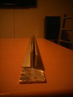
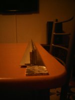
You are right my friend. But this is the solution that i found for the huge strenght. I was inspired by a train bridge when i was on a barbeque. 😎

This night i will assemble the motor structure and will report back tomorrow if it bends. Cant wait.
Cheers
Sergiu
Attachments
You are right my friend. But this is the solution that i found for the huge strenght. I was inspired by a train bridge when i was on a barbeque. 😎
This night i will assemble the motor structure and will report back tomorrow if it bends. Cant wait.
Cheers
Sergiu
yeah that should work, fortify with aluminium 🙂 pulling on the iron
seems to me that elongated riggid structure is going to always have some serious response irregularities. It might be interesting to develop one using a doped fabric, or "pulp" paper/felt material rather than riggid materials. Similar to soft dome constructions.
You may need to experament with the ratio of voice coil mass to diaphragm mass as well. Also the voic coil glues mechanical properties. If use a less hard setting epoxy on VC and a lossy well damped material in the diaphragm, you may be able to smooth out that freq response quite a bit.
You may need to experament with the ratio of voice coil mass to diaphragm mass as well. Also the voic coil glues mechanical properties. If use a less hard setting epoxy on VC and a lossy well damped material in the diaphragm, you may be able to smooth out that freq response quite a bit.
Last edited:
seems to me that elongated riggid structure is going to always have some serious response irregularities. It might be interesting to develop one using a doped fabric, or "pulp" paper/felt material rather than riggid materials. Similar to soft dome constructions.
You may need to experament with the ratio of voice coil mass to diaphragm mass as well. Also the voic coil glues mechanical properties. If use a less hard setting epoxy on VC and a lossy well damped material in the diaphragm, you may be able to smooth out that freq response quite a bit.
Hi lowmass,
I couldnt agree more. But where to get the "pulp" paper or pressed material from?
If i could find some of this material i am willing to test further.
Thanks
Sergiu
Jesus stupid iPhone , I mean a dangerous build allot of force in these magnets
Hello my friend.
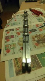
Bad news! The plates bended instanteneusly in a blink.. i tensioned the steel rods at max but it seems that the force is just huuge at 1.4T. The tensioned rods only ads planeity to the steel plates instanteniously after dissasembly the speaker motor.
I have to think at something else. Now the magnets are at 6mm from the steel edges (will increase this at 8mm) and have a 3mm gap (i still want to keep this gap, but will see)..
Cheers
Sergiu
Sergiu, not sure wher u would get such things. BUT u would B suprised at times the reults from making it youself. I try crazy stuff just playing till somthing happens. IDK maybe grind up paper an water in a blender, make paste, apply thin to outside of PVC pipe , dry ... Ha. I always wanted to press a cone from the lint that builds up in the dryer screen. It comes out in nice flat 1/4 inch layers to work with.
Just a thought though, I wonder about long stiff structures, seems there may be a lot of color in sound somewhere if not very well damped , and different materials will change it of course but it seems may be very difficult to overcome to acceptable level??
I suspect paper to have a bit more color than soft dome style, but the low freq resonances of that long voice coil will likley still be issue??
Lay doped silk fabric over PVC, let harden.....
Just thinkin out loud .
Last edited:
Hello Sergiu. A considerable number of people have made both the original, shorter version of M. Deminieres' design and the later, taller version.
As far as I can tell, anyone using the specified dimensions for magnets and mild steel bars had no difficulties with the opposing motors bending into contact with each other, and they definitely didn't have to engineer any additional, reinforcing support structures.
I'm curious what the size is of the magnets and steel bars that you are currently using ?
Thanks, Peter.
Sergiu, not sure wher u would get such things. BUT u would B suprised at times the reults from making it youself. I try crazy stuff just playing till somthing happens. IDK maybe grind up paper an water in a blender, make paste, apply thin to outside of PVC pipe , dry ... Ha. I always wanted to press a cone from the lint that builds up in the dryer screen. It comes out in nice flat 1/4 inch layers to work with.
Just a thought though, I wonder about long stiff structures, seems there may be a lot of color in sound somewhere if not very well damped , and different materials will change it of course but it seems may be very difficult to overcome to acceptable level??
I suspect paper to have a bit more color than soft dome style, but the low freq resonances of that long voice coil will likley still be issue??
Lay doped silk fabric over PVC, let harden.....
Just thinkin out loud .
Hi lowmass
I will try this as soon as i finish the motor.
Cheers
Sergiu
Hello Sergiu. A considerable number of people have made both the original, shorter version of M. Deminieres' design and the later, taller version.
As far as I can tell, anyone using the specified dimensions for magnets and mild steel bars had no difficulties with the opposing motors bending into contact with each other, and they definitely didn't have to engineer any additional, reinforcing support structures.
I'm curious what the size is of the magnets and steel bars that you are currently using ?
Thanks, Peter.
Hi Peter,
I know that others didnt have probs with the motor structure but they used 4mm gap and the magnets are at 10mm dist each (in the front, near the gap) but my magnets are at 6mm from the edge and i have 3mm gap.
I'm using instead of a37 steel (aisi1018), the aisi 1017 wich has abit more iron in it and is a tiny bit more softer....
I have read that others have tryied 3 mm gap on the original Deminiere vers but i know for shure from recently reports that it bended a bit and the paper was rubing.
My magnets are n42 and the originals are n54 neodim standard magnets but the force generated by getting the magnets closer with lets say 1-2mm in the gap is tremendous.
Cheers
Sergiu
I want to tell you my way of thinking in this case Peter: the Deminiere has 10mm+4mm (gap)+10mm (from magnet to edge)=24mm and with 3 mm gap you get 23mm from magnet to magnet. In my case i have 6mm+3mm(gap)+6mm= 15 mm. As you can see here is my problem.. My target is to get between min 1T and max 1.4T force. Every number in this intervall is good for me because i have the 15' bass speakers wich are slighty more efficient than my old version of ruban and i want to make them as close as posssible, i dont want to be in the situation of "cutting" hard into one of them with filters.. I want to conserve that 'eforrtless' sound that they make.
This is what i want.
Thanks
This is what i want.
Thanks
Hello guys,
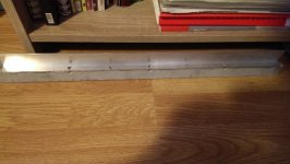
I just wasted my last resort... I glued the magnets at 8mm from the edges (10mm was in the originall ruban) and increased the gap at 4mm and it still bended.... I'm thinking at another solution but till then any advice from you guys will very welcommed...
I think the program femm has a bug or something.. i say this because in this current case, practically, i aproached the magnets with 3 mm and get just 0.15T force in plus, from almost 0.7 to 0.855 T but in reality the plates bends like butter. I think i need a gauss meter at the end to practically see what's happenning here.
The Al "T" that i use for now has 3mm thickness and i dont know how to calculate its resistance at tensionning and what do i need in plus to compensate the brute force generated by the motor.
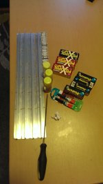
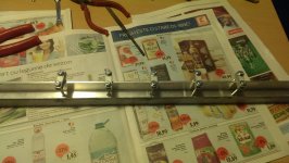
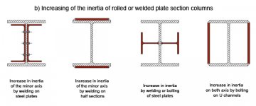
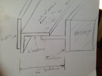
I am thinking to reinforce the "T" 's with four "I" 's at 3mm each like in the first pic from left to right. See the reinforcement example from bellow. So i will have a T with 4 I's, 2*3mm per side. But i dont know if it will work. I dont want to go blind.
Can someone help please.
Cheers
Sergiu
I just wasted my last resort... I glued the magnets at 8mm from the edges (10mm was in the originall ruban) and increased the gap at 4mm and it still bended.... I'm thinking at another solution but till then any advice from you guys will very welcommed...
I think the program femm has a bug or something.. i say this because in this current case, practically, i aproached the magnets with 3 mm and get just 0.15T force in plus, from almost 0.7 to 0.855 T but in reality the plates bends like butter. I think i need a gauss meter at the end to practically see what's happenning here.
The Al "T" that i use for now has 3mm thickness and i dont know how to calculate its resistance at tensionning and what do i need in plus to compensate the brute force generated by the motor.
I am thinking to reinforce the "T" 's with four "I" 's at 3mm each like in the first pic from left to right. See the reinforcement example from bellow. So i will have a T with 4 I's, 2*3mm per side. But i dont know if it will work. I dont want to go blind.
Can someone help please.
Cheers
Sergiu
Attachments
sergiu, trying to get the needed rigidity by making a stiff enough beam is by far the hard way to do this. In fact by the time u get enough stiffness this way u will have a massive and huge magnet structure.
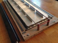
I have built similar speaker designs over the years. In all of them I used a "U" channel with the magnets glued to the inside walls of the U. This sidesteps the huge beam nessasary to resist magnet force.
If you want to use those aluminum "L " you have there U can simply epoxy or bolt them to a flat section of Al or even wood and make a U channel of sorts. This is much easyer using steel however as the magnets will hold to the steel as you try to glue them.
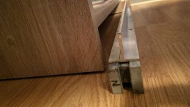
In many of my own designs I used a square tube with flat plates welded or glued to the sides of that, then the magnets glued into the U channel created by this. The pic below doesnt show it well but u can see the U channel at the left. This one made from 1 inch square tube with 1/8 inch steel plates welded on sides extending enough to fit magnets. This way all the riggidity is done by the short distance across the back ( 1 inch tube) , rather than the long distance. Very stiff and easily resists the magnet force
I have built similar speaker designs over the years. In all of them I used a "U" channel with the magnets glued to the inside walls of the U. This sidesteps the huge beam nessasary to resist magnet force.
If you want to use those aluminum "L " you have there U can simply epoxy or bolt them to a flat section of Al or even wood and make a U channel of sorts. This is much easyer using steel however as the magnets will hold to the steel as you try to glue them.
In many of my own designs I used a square tube with flat plates welded or glued to the sides of that, then the magnets glued into the U channel created by this. The pic below doesnt show it well but u can see the U channel at the left. This one made from 1 inch square tube with 1/8 inch steel plates welded on sides extending enough to fit magnets. This way all the riggidity is done by the short distance across the back ( 1 inch tube) , rather than the long distance. Very stiff and easily resists the magnet force
Attachments
Last edited:
Hi Lowmass,
Thanks for the advice. That's why i'm afraid, the huge assembly obtained by reinforcements... But i have to try, i cant go back, because my plates are cuted this way and i cant go back, i have to make this work. The only way to go back is to wait another two weeks for new steel to come wich is not an option for me.
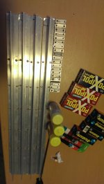
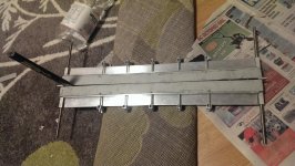
I see your pic so what do you say will be tougher for me from the pics bellow, reinforce with allot of L or I , both or square Al pipes filled with I's insyde?
Thanks
Sergiu
Thanks for the advice. That's why i'm afraid, the huge assembly obtained by reinforcements... But i have to try, i cant go back, because my plates are cuted this way and i cant go back, i have to make this work. The only way to go back is to wait another two weeks for new steel to come wich is not an option for me.
I see your pic so what do you say will be tougher for me from the pics bellow, reinforce with allot of L or I , both or square Al pipes filled with I's insyde?
Thanks
Sergiu
Attachments
Last edited:
Well if your going to forge ahead I would take whatever u have and make I beams. That really is the biggest increase in stiffness.
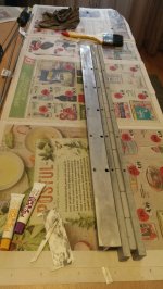
From what I see in both picks I would take the added "L" parts and turn them around to make I beams out of your backbone. In fact I wouldnt be concerned with making the web between thicker but would try to get as much distance between the I beams stressed parts ( the top and bottom plates of I beam). Take the L sections and only overlap with your T section enough to get abunch of screws in there. Maybe overlap only about 1/4 inch. This way you get as tall an I beam as possable. Then use your remaining flat plates to add to the I beam section farthest from the magnets.
The idea is to make as tall an I beam as possable. Cant remember for sure but I think calcs say if you double the Ibeams height you get about 8 X increase in stiffness
Attachments
Last edited:
Thank you very much. 8 times stronger is allot and temting, but there is a BUT wich is that this is the max i can go, no more than 30mm tallness. If i go taller the cilinders will be bigger, and adds increase mass + add too much dampening,... Tested 'the bigger, the better' cilinders theory and posted it in one of my oldest posts and the results werent impressive.
But what if i add two 4 mm I's and two 3mm I's per 'T' (one of each per side to occupy the total of 7mm wich i have now as gap between the perpendicular I from the T and each M5 rod) and bolt everything with glue and allot of steel screws bolted like toothsaw onto the perpendicullar I to prevent further bending? This way i will get 17mm thickness of I's instead of just 3mm like now. What do you think?
But what about a square 30*30*2mm pipe (this is what i found on the market) filled with I's?
Thanks
Sergiu
- Home
- Loudspeakers
- Planars & Exotics
- A DIY Ribbon Speaker of a different Kind