Thanks.
Mile, do you approve the idea of bridging the A40 high power boards?
2 chips per channel.
I made 12, so I got enough.
Because you liked my sound some time ago, I made a video today with my other favorite amplifier.
It is made of garbage items. Discontinued by TVs and any appliances. I used a box of technic with arrows)))))
And for my new A40 I'll make new speakers with those Visaton.
YouTube


These are measurements at 800 mA of the end resistors.
Predictable result 30 watt class A.)))))
However, this is just one shoulder of one channel.
There are 3 more boards for the whole amplifier.


Predictable result 30 watt class A.)))))
However, this is just one shoulder of one channel.
There are 3 more boards for the whole amplifier.
hi there i made A40 by following the schematic. pcb is my own design but i have some issues. offset pot is not working. there is constant high output DC which cannot be adjusted by offset pot. when pgnd is disconnected, there is about 1.5v. i connected the speaker and it gives output but 80% distorted. iam trying to figure out the issue but there is no improvement. i need help.
Hello ,,,,, For ax17, if you use transistor 5200 9, how many volts do you install?
And which component should be changed, if you use high volt?
And which component should be changed, if you use high volt?
FX8 or FH9 is quite low parts count, proven to work well, built by many, and well documented. I don’t know much about AX6. FH9 can be assembled in about an hour.
@burnmaster: Nice work! I haven’t been here in a while so sorry for later replies.
@rehman: you might ask over in main Apex thread.
@burnmaster: Nice work! I haven’t been here in a while so sorry for later replies.
@rehman: you might ask over in main Apex thread.
Hi All. Request your inputs.Which is Apex's lowest part count power amp. Is it AX6 ? Thanks.
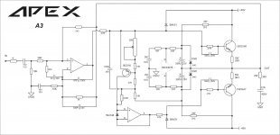
APEX A3
Attachments

Hi All. Request your inputs.Which is Apex's lowest part count power amp. Is it AX6 ? Thanks.
APEX FX4
Attachments
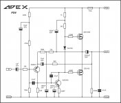
APEX FX4
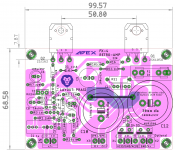
Here is layout posted in retro amp thread.
Attachments
Updated post 1 with FH9 Gerber file with solder pads on both sides.
100W Ultimate Fidelity Amplifier
100W Ultimate Fidelity Amplifier
PSU and Protection
Any help with PCB pdf for this PSU please
Thank you Karl vd Berg,
I just updated the first page directory with the above 2 preamps and also a PAU + stereo protect circuit I saw on same page.
The schematics are really adding up so far! 🙂 Count is currently 43 schematics on Post 1.
PSU and Protection:
Any help with PCB pdf for this PSU please
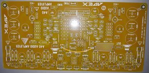
I don't know if this is the best place to post but I would like some advice/help with A40. I went ahead and ordered the PCB attached in the A40 build thread but it looks like there is a problem.
I have attached pictures of shorts on the front side.
I assume I should dremel away the top copper trace. (The gerber files in this thread have a top copper layer with one copper arc.) It looks like the amplifier will badly malfunction with the shorts to the bias trimmer and resistor.
Perhaps this post can serve as a warning to others regarding the gerbers in the A40 build thread. I hope that the amplifier works when assembled with these PCB after the dremel fix. The parts are fairly expensive for two of these boards so I hope the gerbers attached to this thread are good... If there are other problems with the gerbers I would appreciate a warning before I waste all the components and time assembling this.
Attachments
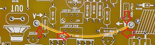
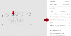
Looks as if the top copper trace was to be a wire jumper so looks as if you have to isolate it, cut out any shorts that the Cu trace creates
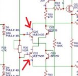
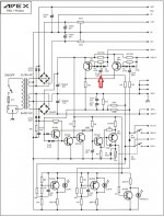
re you sure that in Apex A40 exactly bd139 should be on the radiator? They are in the mode of diodes... Maybe those mje340/350 that are connected to them in series
Attachments
Last edited:
- Home
- Amplifiers
- Solid State
- A Directory of Apex Audio Amplifiers