Supposedly my transformers were delivered today. Does someone have link to instructions as to how to characterize them and make all critical measurements? Winding resistance is relatively easy... and I can run the bode plots using the audio generator and digital scope. Inductance measurements and the inter-winding capacitive losses might be a little more complicated… I have a general radio 1650 LCR bridge that I’ve not had use for yet. I need to look over the internal generator for it, and try to check calibration too. I have HP 200AB audio generator, so can measure at any frequency.
When driving with triodes the low rp of the triode minimizes any problems we might have with the OPT at the LF end.Supposedly my transformers were delivered today. Does someone have link to instructions as to how to characterize them and make all critical measurements? Winding resistance is relatively easy... and I can run the bode plots using the audio generator and digital scope. Inductance measurements and the inter-winding capacitive losses might be a little more complicated… I have a general radio 1650 LCR bridge that I’ve not had use for yet. I need to look over the internal generator for it, and try to check calibration too. I have HP 200AB audio generator, so can measure at any frequency.
For the frequencies above 10 KHz the leakage reactance is still a problem.
I've for the most part ignored the high end problems & simply charged ahead & built whatever amp it was.
Then fix the problems, Back in the dark ages we had no simulators to waste our time.
even without simulations, I'd still like to be able to measure the frequency response of these transformers to see how they will affect performance!When driving with triodes the low rp of the triode minimizes any problems we might have with the OPT at the LF end.
For the frequencies above 10 KHz the leakage reactance is still a problem.
I've for the most part ignored the high end problems & simply charged ahead & built whatever amp it was.
Then fix the problems, Back in the dark ages we had no simulators to waste our time.
well, unsurprisingly, the power toroids don't show good frequency response with high source impedance. 56K load in series with the generator, and the frequency response of a single transformer is not much to write home about past 20khz. with 10K source impedance, it does much better. I don't have enough aligator clips in the same place as the computer with the test gear, so will have to do more serious tests tomorrow. I also forgot to grab anything but a 16R resistor to act as a load on the transformer, so not sure if it will affect things negatively or not.
+1 for triode amps for having inherently low source impedance, compared to pentodes, I guess?
+1 for triode amps for having inherently low source impedance, compared to pentodes, I guess?
Your HP 200AB covers 20 Hz to 40 KHz at 600 Ohms impedance.
so simply driving your OPT with that will give some idea of performance.
Load the secondary of the OPT with the load you intend to use,
If leakage reactance is significant the HF will drop off.
The LF will probably be OK. As a further test you could try driving the
OPT thru a resister, say 5K. The LF would be something like what
you would see in pentodes were used in the output stage.
The output load of a pentode stage assumes the reflected impedance of
the load on the secondary,

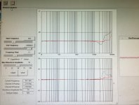
Here are the plots of the a antek 5000k:8R 15 watt purpose wound output transformer. 16r load on 8ohm transformer tap. Will do again tomorrow with appropriate load resistors
Comparison of the two lines on the upper chart is amplitude vs frequency with 56k and 10k in series with the generator that is built into the syscomp circuit gear mini USB scope. The 10k line is the flatter of the two.
So if what I’m understanding from you is correct, 10k is more than adequate to use in measuring the worst case response curve, if the reflected load would be 5k from a speaker, regardless of whether pentode or triode driving the transformer? If that is the case, using the 56k load is just making things look needlessly bad, and maybe the mains toroids won’t perform so badly after all? They looked not too much worse than the purpose wound output transformer at 56k source impedance.
Attachments
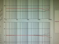
Gray plot is the MP-15W50, red is a single AN-0215 transformer with primaries in series, and secondaries paralleled into 16R. The dip at 24khz is about 2.4dB.
These are both with source impedance of ~10k
I’ll do tomorrow with 4R load for the AN-0215, along with the interleaved primary windings and two transformers as used by @kodabmx, and see what it looks like, and of course proper 8R load for the MP-15W50.
These are both with source impedance of ~10k
I’ll do tomorrow with 4R load for the AN-0215, along with the interleaved primary windings and two transformers as used by @kodabmx, and see what it looks like, and of course proper 8R load for the MP-15W50.
Attachments
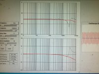
Here are frequency response plots for the stack-o-donuts. I interleaved the primaries from the two transformers all in series, with the secondaries all paralleled. This is the 25va antek toroid. Gray plot is with 10k source load, red with the 150 ohm source impedance of the generator. Both plots into 4 ohms.
I measured on one of the 50VA transformers, and found that the turns per Volt on the secondary is about 8, with 115v on one of the primaries. I may need to take off the belly band in order to wind on extra secondaries so as to be able to get 4 ohm and 8 ohms on the outputs. Did not get a chance to measure turns per volt on the 25va models.
I measured on one of the 50VA transformers, and found that the turns per Volt on the secondary is about 8, with 115v on one of the primaries. I may need to take off the belly band in order to wind on extra secondaries so as to be able to get 4 ohm and 8 ohms on the outputs. Did not get a chance to measure turns per volt on the 25va models.
Attachments
Series resistance of the primaries is about double that of the 50VA transformer. The 50VA units have “belly rings”, which I imagine would interfere with adding wire to the secondaries for an 8 ohm speaker load. I will be taking the outer insulation from one of those at some point to see if I can easily add wire to the secondaries.
- Home
- Amplifiers
- Tubes / Valves
- A different kind of triode amplifier...