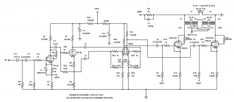
I don't see any problem with transformer current, it's standard push pull 🤔. The driver currents still balance out. You still need to drop the input stage and phase splitter supply voltages, you don't have 450V anymore. Something like the attached, which also shows how to connect the feedback with an led (or bypassed resistor in its place).

See #2. He's been clearly speaking of and showing in his schematics four individual mains transformers as a replacement of a PP output tranny.
Best regards!
Best regards!

I’m looking at trying a pair of mains toroids with the all four primaries in series, but pretty sure I’ll be using proper output transformers in the end. The more I play with this, the more I am reminded there is no free lunch 🙂
If you try a pair of mains toroids, I suggest you wire the primaries like this: It works much better for LF response (full power at 25Hz instead of 50Hz for instance).

Last edited by a moderator:
It was your posts on the topic that got me interested in the idea. Cheap 50% UL tapped transformer. In the sims I made of this amp, I noticed that you get better distortion figure from using the ultra linear transformer for the bootstrapping than you do from the resistor method, but with resistors/voltage divider, it gives opportunity to control which harmonics dominate the amp, as some of the signal bleeds through and the PP amp no longer eliminates even harmonics to the same extent.
I’m still trying to see if there is a way around the cathode biasing issue. 56w for a stereo amp just to do the bias is a little absurd, though it would be great in the winter time.
I’m still trying to see if there is a way around the cathode biasing issue. 56w for a stereo amp just to do the bias is a little absurd, though it would be great in the winter time.
Yup... Have you tried no bootstrap but double voltage to the driver? Maybe you could just use fixed bias that way? The last time I used 6080 etc I used them as cathode follower output. If you can make say 300V PP (I did it in all my modular amps but it leaves no room for NFB) it might be an idea. I know that's completely different from this design though.
It doesn't work out so well with massive driver voltage. It clips the drivers before the outputs if I'm remembering correctly. everything seemed worse without bootstrapping.Yup... Have you tried no bootstrap but double voltage to the driver? Maybe you could just use fixed bias that way? The last time I used 6080 etc I used them as cathode follower output. If you can make say 300V PP (I did it in all my modular amps but it leaves no room for NFB) it might be an idea. I know that's completely different from this design though.
Getting closer! Thanks to a question from Ketje, I decided to try with the extra bootstrapping that comes from connecting to the plate windings directly instead of just at the UL tap. This achieved positive results in terms of being easier to drive, and showed an improvement of distortion numbers. Most of the distortion at higher output levels seemed to be coming from clipping of input stages or the driver, and easing the driver’s job only seems to help in this regard.
the only way I could get enough difference between the input tube and the phase inverter and achieve direct coupling and headroom to spare, was with a 6dj8/ecc88. I did some iterations with the bootstrapping coming direct from the plate windings and found it to be superior in terms of being yet easier to drive the 6089/6as7 fully so that it would clip before anything else in the circuit. I am still learning, so if having the output tube clip first is poor practice, I’m open to suggestion. This version and the parallel output version of the same have sensitivity to 1.55v for drive to the output tubes that will be hitting the limits of the grids being driven to zero.
Today I dug around in my small pile of 6080 and 6as7 tubes and checked three of each on a tube tester for balance. Some were terrible with one Section at 66 and the other 78 or so. Some other tubes were much better matched at 77/78. I will have to check at actual circuit voltages and currents to see if this holds up, or if it’s just at the tube tester‘s operating point. I only have a few new in the box tubes of these varieties, unfortunately, but every used one that I have tested has had plenty of life in it still. I considered for PPP design, that one could use an unbalanced tube with a similarly unbalanced tube, and get relatively good output. For proof of concept, I will make a simple output stage with one tube per channel, rather than parallel push pull.
I was hoping to make a pair of mono amps, but since I can’t find any tube better than 6dj8/ecc88 for the input stage, I may just have to build in stereo. I’m not at all worried about the drivers and outputs needing 320V, while the voltage amplifier and phase inverters need 400/425V. a second supply that is only feeding the 10ma or so to those two tubes (or one tube if I find something suitable) shouldn’t be too much extra work.
John Stewart, if you’re still watching this thread, I’m curious why you decided to use the UL taps for the bootstrapping rather than directly from the plate windings as in the circuit I posted above. Is there some disadvantage that I’m not seeing that will come from this extra positive feedback?
regarding the partial fixed bias, I read somewhere today that there is a datasheet out there for the 6080 or 6as7 where they mentin partial fixed bias is ok so long as 1/3 of the bias is from a cathode resistor, so it looks like I’m close, but may need to tweak things a bit. My plan to test this is to build That part of the circuit and run it from a regulated power supply, and vary the plate voltage plus or minus some 10-20% to simulate a load on the amp’s supply and see if the bias stays regulated enough. I’m not sure how to make even a crude bias servo yet, but was looking at differential amps using 6j6 tubes of which I have many. They only need a 1/4 watt or so of heater power, so would be much more efficient to run than pure cathode bias if I could get them to do anything useful to help keep the 6080 tubes from thermal runaway.
Still not sure why you need the high voltage for the input and PI stage, the voltage swings are only modest as all the hard work is done by the drivers. Post #41 used 6SN7s and there was plenty of headroom. Do you minding sharing your .asc file and the models you are using?
The RCA datasheet for the 6080 says for combined bias, the cathode bias part should have a minimum of 7.5V DC. You are well above that so I guess it should be fine.
The RCA datasheet for the 6080 says for combined bias, the cathode bias part should have a minimum of 7.5V DC. You are well above that so I guess it should be fine.
This iteration of the circuit shewed up on the iNet about 2 yrs ago.John Stewart, if you’re still watching this thread, I’m curious why you decided to use the UL taps for the bootstrapping rather than directly from the plate windings as in the circuit I posted above. Is there some disadvantage that I’m not seeing that will come from this extra positive feedback?
Don't know if its still a dream or anyone had tried it tho.
Attachments
I found initially that I needed close to 12 volts of swing on the driver grids at maximum output, to make close to 250v pp to fully drive the grids of the 6080 tubes, which are biased at -125v. I may have reduced that need a bit by bootstrapping direct from the plate leads on the output transformer. I will check again working backwards from the driver stage to see what voltages are needed. I wanted some headroom to account for variances in tolerance in tubes and other components, and I may have been too generous in that regard with the tolerances. I’ll try to post the actual files today or tomorrow.Still not sure why you need the high voltage for the input and PI stage, the voltage swings are only modest as all the hard work is done by the drivers. Post #41 used 6SN7s and there was plenty of headroom. Do you minding sharing your .asc file and the models you are using?
The RCA datasheet for the 6080 says for combined bias, the cathode bias part should have a minimum of 7.5V DC. You are well above that so I guess it should be fine.
it Is much easier to couple the input to the phase inverter with a capacitor, and such large voltages weren’t needed, but it hurts bandwidth and I guess stability too? That’s an area of circuit design that I don’t claim to fully understand at the moment. In order to remove that capacitor, and still have adequate headroom to prevent overloading the front end and phase inverter, I needed relatively higher voltages. Maybe someone with more experience can make it work with less. I definitely don’t want this circuit to be finicky about tube tolerances, so not trying to run everything at the ragged edge, except maybe the output tubes 🙂
Who told you so? And do you have a clue why?I am still learning, so if having the output tube clip first is poor practice, I’m open to suggestion.
Best regards!
Someone talking on this forum, I think 🙂Who told you so? And do you have a clue why?
Best regards!
it had to do with blocking of the signal when the grids went positive, and the “long”, and hence audible recovery time before the capacitor feeding that stage would finish discharging. Maybe I’m not understanding correctly, though?
nobody told me having the output tube clip first was bad. I read that having input stages reach maximum headroom first was more problematic. Happy to learn if I’m not understanding good design practices!Who told you so? And do you have a clue why?
Best regards!
A few things I have come to understand more recently based on teachings of others:
bandwidth past the audio realm is important to good transient response.
too much feedback or not enough feedback is not particularly good. Either use a little, or the amount needed by op amps (Hard to implant with tube circuits, so a little is probably better. I read that the higher harmonics start to be emphasized more with increasing feedback, thiugh I have yet to model a circuit where I see this happening, and don’t have measuring devices sensitive enough to see it happening in real life, except perhaps my ears, which I only partly trust to be trained enough to know.
some people like 3rd harmonic distortion better than second. some people prefer none. Everyone perceives things differently, but we can probably measure why a circuit is producing pleasing or unpleasing sounds if we are smart and through in our analysis and have adequate measuring tools to run experiments and take data.
the room and the speakers are the most important part of the audio chain, followed by the source and the preamp. This is part of why I’m working on a power amp to learn, since if I stuff it up, it won’t sound as miserable as poor speakers, or a crappy and noisy phono stage 🙂
some extra wattage in the amp allows cleaner reproduction of transient peaks in recorded sound, so you want an amp that starts distorting slowly/progressively, rather than suddenly hitting a brick wall, and you want recovery from any distortion from transients to happen as quickly as possible (but best not to hit that wall in the first place!).
on my own, from repairing electronic devices, and just common sense, I have long ago realized that I like circuits that are relatively forgiving of component tolerances. There is a trade off between performance and component tolerances needed to maximize it, but there is something like an exponentially diminishing rate of return in this regard, where to wring more power or accuracy from a given system, you need ever more complex circuit topology and ever more tightly controlled components, power supply, etc, in order to achieve the goals. There are also diminishing rates of return on perception, whereby for most people with “normal“ hearing, there is a diminishing rate of return on how much more enjoyment of the music one might get from an ever more complex and expensive sound system. That said, I have experienced something like sound nirvana from the synergy (man I hate that term and how it’s abused!) of a system where the source, amplification, speakers, and room all played together to create magical sound experiences. Sometimes it’s a lowly console amp and the crappy console speakers, sometimes it’s a top dollar, high end stuff. I like to listen to all sorts of music, and as long as the sound reproduction is not getting in the way of the enjoyment of the music, it’s good enough. Sometimes a low-fi wind up Victoria will bring you to your knees, sometimes you need subwoofers that could shake loose a kidney stone. It all depends.
- Home
- Amplifiers
- Tubes / Valves
- A different kind of triode amplifier...