Hi Mona,Suggestion, make R31-R32 39k and leave out R4 and R5.
Mona
R4 and R5 were added by John to maintain stability when feedback was applied.
I can’t remeber why I picked 10k for r31 and 32. I will look at that version again. I was trying to see if I could maximize power out while keeping distortion down to try to match performance of the design with the UL transformer for bootstrapping taps.
I’ll post up what I’ve got worked out with partial fixed bias later today.
I looked at the simulation again, and I see that I have R31-R32 at 10K because that is what gave the cleanest output. increasing those resistors puts a damper on the amount of feedback to the drivers, and causes a marked increase in distortion.Suggestion, make R31-R32 39k and leave out R4 and R5.
Mona
Why do you recommend making them 39K?
R31&R32 are a feedback for the final stage and an extra load for the driver. If to small the driver isn't capable of outputing enough voltage swing to drive the output to the fullest.
And R4-R5 make things worse by reducing the working voltage of the driver.
Mona
And R4-R5 make things worse by reducing the working voltage of the driver.
Mona
Thanks for the explanation. I will look into this some more.R31&R32 are a feedback for the final stage and an extra load for the driver. If to small the driver isn't capable of outputing enough voltage swing to drive the output to the fullest.
And R4-R5 make things worse by reducing the working voltage of the driver.
Mona
R31&R32 are a feedback for the final stage and an extra load for the driver. If to small the driver isn't capable of outputing enough voltage swing to drive the output to the fullest.
And R4-R5 make things worse by reducing the working voltage of the driver.
Mona
regarding r-31/32, it turns out, at least in simulation world of the circuit as it currently stands not to make too much difference. There are minor shifts in harmonic distortion distribution, and minor shifts in the input voltage level needed to drive the amp.
I managed to design something with concertina phase splitter, and refined the driver stage a bit. Only negative voltage now is for the bias supply. I started trying to use the 6U8a family of triode/pentodes, but couldn’t get the spice model for the pentode section to work correctly. So I switched to 6sn7’s as voltage amp and phase splitter. I realized the the phase splitter needed to have a relatively big grid voltage swing in order to handle possible overload conditions with grace. The 6sl7 couldn’t do it either. 6u8 triode was pretty good, but suffered from more third harmonic distortion than the 6sn7.
lastly, I came up with a way to give B+ to the driver stage in adequate amounts. I added two chokes from b+ to the plates of the drivers. This solves a bunch of problems, and since they only pull a small amount of current, it shouldn’t be too expensive to source them. As I was dropping them into the model, I realized that I was getting dangerously close to inventing the Macintosh unity coupled circuit. Give a monkey (or maybe 1000 monkeys?) a circuit simulator, and eventually they’ll create something worthwhile 😆
I think this is going to work nicely. Distortion both with and without feedback is even lower than the initial model I made, and it needs a scant 2.15V in for 25W rms out With feedback, less than 1v with no feedback. Visible Clipping seems to happen in the drivers and output stage, simultaneously and gently, with heasroom to spare at the input ano phase splitter. With feedback hooked up, It takes a Little under 2.75 volts before the wave peaks start to flatten. the design with the UL transformer has slightly better 3rd harmonic levels, but overall slightly higher drive requirements for the same power out. If using the transformer as intended at 4.3k primary impedance (which is 2x what the circuit wants), it only rally has a penalty in driving voltage, but it handles distortion and overload nicely still, which makes me hopeful that it will behave when driving a speaker load, rather than just a resistor In a simulation.
The Different Kind of Triode Amplifier circuit was not optimised. The circuit is simply proof of concept.Hi Mona,
R4 and R5 were added by John to maintain stability when feedback was applied.
I can’t remeber why I picked 10k for r31 and 32. I will look at that version again. I was trying to see if I could maximize power out while keeping distortion down to try to match performance of the design with the UL transformer for bootstrapping taps.
I’ll post up what I’ve got worked out with partial fixed bias later today.
I ran a simulation yesterday on the 2-stage driver without the benefit of the bootstrapping provided by the output PP stage.
The balance at the output looks very good. And if the 6080s were matched the balance would be better.
An AC balance adjustment would be a positive addition.
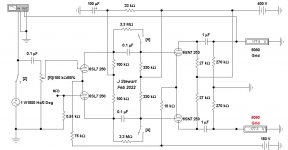
A switch controlled by key 'A' is inserted to check the effectiveness of R4 & R5.
They do not do much as the amp was built. That entire network needs to be setup for whatever OPT is used.
When this circuit was first run more than 20 yrs ago the 6080s were JAN. I gave away a large chunk of my stash just before COVID.
The tubes I pulled out to run this time are Mullards, new out of the carefully wrapped boxes. These are clipping at ~20 Watts.
I ran PP 5998s with partial fixed bias a while back. The 5998 triodes have a mu of ~5 so that the cathode resister heat was not a problem.
But the trial worked well.
In your most recent Sim of the circuit R31 to R34 will waste some of the audio power at the output.
The Audio signal across them is in series with the load.
Hammond have a 60H, 8 mA choke that would work in the 6SN7 plate leads.
But that will introduce a 12 db/octave LF corner into the audio path. That could be difficult to control with NFB.
Attachments
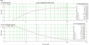
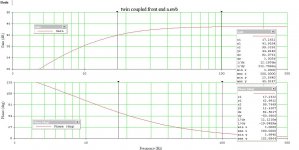

I just put 50H as an arbitrary number to see if it would work in principle. I need to test frequency response and see what happens. I have not explored that aspect of spice yet, though I have a way to do it in real life.
it’s too bad there isn’t a plethora of 5998 tubes out there to be had! Or even better 6528! It’s a shame with all of the reproductions being made, nobody is churning out these slightly higher mu power triodes.
it’s too bad there isn’t a plethora of 5998 tubes out there to be had! Or even better 6528! It’s a shame with all of the reproductions being made, nobody is churning out these slightly higher mu power triodes.
The image in the previous post is from the cathodes of the original design. with feedback, and driven to 25W rms output, the signal is too large, both for the input, and the inverting input of the LTP. I have been running into the same problem with this while trying to put a Split load (concertina) phase inverter on the front end of the amp. 25W seems about as far as you can go with two tubes in PPP before the grids of the output tubes (at about -125V) are driven positive.
I managed to eek out enough headroom to prevent the inputs from clipping. I think my problem was in the phase inverter and in the drivers. I also found a handy way to not need any chokes, and got me back to seeing how brilliant the original design is. Now that I can drive this in the simulation until the output tubes can’t output any more, you can see just what a boon the bootstrapping is and how nicely it solves the problem of driving these tubes.
I wanted to decouple the supply for the 6sn7’s driver so that I could try using partial fixed bias, and see in real life if one could save a sizable amount of heat lost/wasted by running these tubes at “high” plate voltage, and what are really obscene levels of drive needed. At some point I had an a-ha! moment, and realized that I could us keep the final stage functioning with the bootstrapping, while still providing adequate voltage supply to the drivers. It simply involves adding 150v positive to the cathodes resistors of the 6as7’s. These tubes have a very robust heater-cathode insulation, and are rated for the cathode to be 300volts positive or negative to the heaters. Lifting them 150 volts shouldn’t be any problem at all. And the bonus of this, is that it allows for the plate supply of the drivers to be raised a little too.
with 450v b+, you have more than enough for the drivers, and still have plenty of headroom for the grids of the drivers. Results in the simulation look very nice, and there are no chokes or other shenanigans. Notes at the top of the schematic show wattage at clipping, and distortion makeup at clipping. Hopefully I can get close to this in real life 🙂
36w rms of relatively clean sound from a pair of 6as7 running ppp, would be pretty neat, and worth the heat. I undid the bootstrapping and looked at what was happening, and saw clipping happens in the drover stage first. It runs out of b+ headroom, and starts clipping hard with very little watts out if you feed just 400v to the drivers. Like 15w distorted audio That would be better at heating your house than making music. It’s easy to see why almost every amp I’ve seen someone make with 6080/6as7 tubes has been terribly frustrated by it. I raised those supplies to 600v, which runs up to the maximum plate voltage for the drivers, and still could only get 25w rms out before it got really ugly. with the bootstrapping, you get voltage swing at the drivers over the value of the plate supply. It’s like using a choke input supply with none of the downsides. The design below showed peaks of 484.5V with a plate supply of 450. The drivers sit at 344v at idle. Magic, that with appropriate circuit design, you can exceed supply voltage without clipping. Hats off to John Stewart for coming up with (or at least successfully applying it to triodes!) and championing this design. The bootstrapped version is also capable of giving distortion levels right up to clipping that are better than an ordinary 6as7 amp would have at significantly lower watts out if it were easier to run these in A2, you could probably squeeze a few more watts from them.
I poked around in data sheets and tube manuals, and couldn’t find any other tubes that might make better drivers than the 6sn7. Not many easy to find tubes that can handle 450v on the plate and have grid control that extends that low. I’ve got my eye on some other tubes to use for the voltage amplifier and phase splitter, so as not to use up tubes that are terribly expensive, when something else will do. You need bias of 15v or more in order to provide enough drive to the drivers to swing +/- 250v for the output tubes, which might be a little difficult to source, but I’m sure there’s something out there in the world of dissimilar duo triodes.
I might have deleted something in the bias circuit by accident... or maybe it works as is? I’ll have to check tomorrow to see. Either way, it worked beautifully in the simulation, and was adjustable over a relatively wide range. hopefully the partial fixed bias will work in real life too! Next step is to see again what happens with using the voltage divider setup to eliminate the UL transformer, and compare notes. I might see if I can increase the sensitivity a bit more without having to add another stage at the front end Something with ability to bias at 5-6v cleanly, but with bigger Mu than the 6sn7. this is where those dissimilar duo-triodes come in. It might also afford more feedback, but at the moment, the level of distortion seems very acceptable in level. With controls installed to allow balancing of the driver, and to allow for some in circuit matching of the 6as7’s maybe I can get close to the performance of this simulation.
The extra resistor and tiny capacitor on the cathode of the phase inverter are to compensate for a slight difference in the high frequency response due to (I think) different impedance of the plate and cathode Inherent to the split load phase inverter. Not sure that it matters, but I corrected for it in the simulation because I could, and to help me understand what corrections I may need to make in real life construction. I know way too little about filters and frequency/phase compensation, but with a tool like spice, even a stupid ape can run endless iterations in short order and come up with a possibly functioning solution.
I don't think you can just "add" 155V to the output cathodes - what is dissipating the power? Better to connect R18/R19/R22 to -150V, drop B+ back to 300V, and use a negative bias voltage for the output tubes. I also think you could increase R12 and decrease the input stage current so that there is ~90V on the first stage anode so you can direct couple to the phase splitter. Also bypass most of the input stage cathode resistance (or use an LED) to increase gain.
Ok, point taken regarding the extra positive power supply... easier to make a low current -150 supply than to do the other way around and have high current supply in the cathodes of the drivers. I will need to lift the heater supply for the driver stage to not violate heater cathode voltage, but again, much easier than two high current supplies to feed the drivers.I don't think you can just "add" 155V to the output cathodes - what is dissipating the power? Better to connect R18/R19/R22 to -150V, drop B+ back to 300V, and use a negative bias voltage for the output tubes. I also think you could increase R12 and decrease the input stage current so that there is ~90V on the first stage anode so you can direct couple to the phase splitter. Also bypass most of the input stage cathode resistance (or use an LED) to increase gai
I was having trouble keeping the voltage on the phase inverter correct when adjusting the input stage to try to directly couple them. I'll look into that some more.
here the version with negative supplies, starting to look more like the master's work than the student's (John used negative voltage applied to the LTP for his original design):
When I bypass the input stage cathode resistance, it kills the low frequency response, since the feedback is connected there. *edit - if there's a better place to connect the feedback, I'm open to suggestion.Also bypass most of the input stage cathode resistance (or use an LED) to increase gain.
I'm not morally opposed to transistors, but other than power supply rectifiers, I'm trying to go full hollow-state active devices in the circuit.
I see an even bigger isue: Any of your transformers will see massive DC current through it's primary that will lead into core saturation even at small output levels.
Best regards!
Best regards!
and now another little damper on the euphoria 🙂
it probably clips hard closer to 25W, as this is the power level at which the grids are swinging positive on the outputs. The things the model isn't programed for, it most likely cannot discover.
it probably clips hard closer to 25W, as this is the power level at which the grids are swinging positive on the outputs. The things the model isn't programed for, it most likely cannot discover.
how massive is 8ma for the driver tube?I see an even bigger isue: Any of your transformers will see massive DC current through it's primary that will lead into core saturation even at small output levels.
Best regards!
For the output tubes it is 130mA DC x2, which is less than half of what the hammond 1650N can handle per side. I'm guessing that Edcor and others also make transformers that can handle this level of current in the primary? any 50W or so output transformer should handle this with ease, and some smaller ones too. or did you mean for my crazy idea of lifting the output tube cathodes with a second power supply?
- Home
- Amplifiers
- Tubes / Valves
- A different kind of triode amplifier...