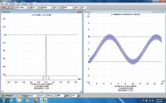
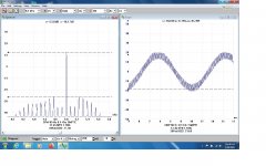
Here are some actual test results from today on this experimental PPP 6080 Bootstrapped Amp. Still looks good running with Mullard tubes.
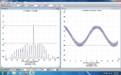
But an AC Balance control would help a lot, looks like the 6080s are not well matched at all.
How does this compare with the favorite toob amp of others?
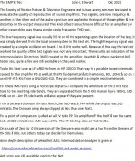
For those not familiar with the SMPTE test method a description is included.
SMPTE is more difficult for an amp to pass. But common in some fields, like Motion Pictures.
But an AC Balance control would help a lot, looks like the 6080s are not well matched at all.
How does this compare with the favorite toob amp of others?
For those not familiar with the SMPTE test method a description is included.
SMPTE is more difficult for an amp to pass. But common in some fields, like Motion Pictures.
Attachments
-
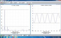 PPP 6080 One Watt 1000 Hz.jpg142.2 KB · Views: 79
 -
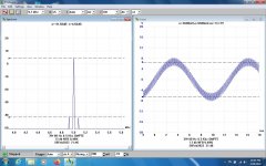
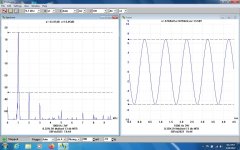 PPP 6080 3W 1000Hz.jpg150.4 KB · Views: 72
 -
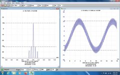
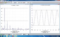 PPP 6080 10W 1000Hz.jpg153.8 KB · Views: 75
 -
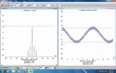
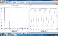 PPP 6080 15.9W 1000 Hz.jpg154.7 KB · Views: 70
 -
 PPP 6080 One Watt SMPTE.jpg147.8 KB · Views: 72
 -
 PPP 6080 3W SMPTE.jpg147.3 KB · Views: 70
 -
 PPP 6080 10W SMPTE.jpg153.3 KB · Views: 70
 -
 PPP 6080 15W SMPTE.jpg148.6 KB · Views: 77
 -
 PPP 6080 20W SMPTE.jpg158.9 KB · Views: 74
 -
 PPP 6080 25W SMPTE.jpg173.5 KB · Views: 78
 -
 SMPTE Test System.jpg147.3 KB · Views: 78

I’ve got a 200AB in pretty fine fettle (though could probably use better matched output tubes). I just got a 200CD for cheap from the auction site, that I’ll need to go over before using. Thanks for posting these test results, and explaining how it’s done.
John, where would you put an AC balance control in your original design? And with the push-pull driver, obviously that tube would do better if it is matched also. Would one put a control in to adjust the balance of the driver stage, and use that to also balance the output tubes, or would it be superior to have a way to balance both the driver and the outputs separately from one another?
John, where would you put an AC balance control in your original design? And with the push-pull driver, obviously that tube would do better if it is matched also. Would one put a control in to adjust the balance of the driver stage, and use that to also balance the output tubes, or would it be superior to have a way to balance both the driver and the outputs separately from one another?
Regarding unequal amplitudes on the first dif pair output. I also observed this and it's contribution to second harmonic distortion. A simple trick I rediscovered is linked in an earlier post of mine.
https://www.diyaudio.com/community/threads/long-tail-pair-current-source-trick.379834/#post-6859283K
This is my first attempt in linking, so I hope it worked correctly. See the first post.
https://www.diyaudio.com/community/threads/long-tail-pair-current-source-trick.379834/#post-6859283K
This is my first attempt in linking, so I hope it worked correctly. See the first post.
John, where would you put an AC balance control in your original design? And with the push-pull driver, obviously that tube would do better if it is matched also. Would one put a control in to adjust the balance of the driver stage, and use that to also balance the output tubes, or would it be superior to have a way to balance both the driver and the outputs separately from one another?
I didn't put any AC or DC balance or other adjustment into the Diff Triode Amp.
It was strictly an experimental brain storm. All it was meant to do was prove the idea was viable & worked.
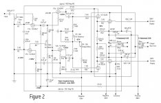
The attached is an example of what I've used in other amps. P3 near the center of the schema works very well.
And would be a good addition to the Diff Triode Amp.
I've been pondering another AC Balance control for a while, something that avoids current passing thru the wiper
in a pot. I'll put that on DIY soon.
The scheme in the linked article looks interesting. Some have tried with varying success.
I didn't put any AC or DC balance or other adjustment into the Diff Triode Amp.
It was strictly an experimental brain storm. All it was meant to do was prove the idea was viable & worked.
The attached is an example of what I've used in other amps. P3 near the center of the schema works very well.
And would be a good addition to the Diff Triode Amp.
I've been pondering another AC Balance control for a while, something that avoids current passing thru the wiper
in a pot. I'll put that on DIY soon.
The scheme in the linked article looks interesting. Some have tried with varying success.
Attachments
Here is the working model for what I had so far. I may be misunderstanding how the direct coupled split load phase inverter works, regarding biasing it to handle the signal from the previous stage. I read some stuff about direct coupled stages on merlin the valve wizard's pages, that makes me think that the bias may be more self adjusting than I realized, but I need to read it all one or two more times to get it straight in my head. I need roughly 12.75V out from the phase inverter to get the drivers to swing fully to 250V to drive the output tubes at maximum swing.
An interesting proposition would be to add a cathode follower stage after the driver in order to allow the 6080 tubes to run in A2, but I'm not sure what tubes other than more 6080 tubes could pull that off, and there's diminished returns in the watts in vs watts out that start to manifest.
An interesting proposition would be to add a cathode follower stage after the driver in order to allow the 6080 tubes to run in A2, but I'm not sure what tubes other than more 6080 tubes could pull that off, and there's diminished returns in the watts in vs watts out that start to manifest.
Attachments
the combined bias and 7.5V dc tip are for specific service as a DC amplifier. I'm not sure if that will carry over to use as an audio amp? The problem becomes, that the lower the cathode bias, the harder it is to provide adequate voltage to the drivers.Still not sure why you need the high voltage for the input and PI stage, the voltage swings are only modest as all the hard work is done by the drivers. Post #41 used 6SN7s and there was plenty of headroom. Do you minding sharing your .asc file and the models you are using?
The RCA datasheet for the 6080 says for combined bias, the cathode bias part should have a minimum of 7.5V DC. You are well above that so I guess it should be fine.
Fortunately the input and PI stages draw very little current, so it ought to be easy enough to use a small and relatively inexpensive transformer to feed the higher B+ to those tubes. with the relatively affordable Antek mains toroids there isn't enough heater current available for putting all the tubes on one transformer anyway, so short of adding a heater winding to an existing mains transformer, it makes some sense to use two power transformers, get two B+ voltages, and get some extra current to feed the heaters. I'm mulling over building separate supplies for each channel, but may only do separate supplies for the drivers/outputs, since the input/PI and bias are pulling so little current and won't suffer from power supply compression like the outputs will. Part of me wants to keep it simple and use a single 6080 in PP for the output, but part of me looks at the extra power/headroom to be had with the relatively simple job of adding a socket and a few extra components plus beefier (or dual) power transformers for the outputs.
I've made a few changes:
- Some statements to improve accuracy for distortion measurement
- distortion measurement of output - view spice error log to see
- lowered front end B+ to 300V and adjusted resistor values to suit. Distortion improved 🙂
- bypassed input stage cathode resistor to increase gain
- Used common tail resistor for LTP, no bypass required
- Used some different models, included in .asc file.
- Your original sim had ~22W out for 1.5V in (peak). This is still the case. Output clips at 1.7V in, ~27W.
Attachments
Hi tikiroo,I've made a few changes:
- Some statements to improve accuracy for distortion measurement
- distortion measurement of output - view spice error log to see
- lowered front end B+ to 300V and adjusted resistor values to suit. Distortion improved 🙂
- bypassed input stage cathode resistor to increase gain
- Used common tail resistor for LTP, no bypass required
- Used some different models, included in .asc file.
- Your original sim had ~22W out for 1.5V in (peak). This is still the case. Output clips at 1.7V in, ~27W.
Thanks for looking at this! I will check later on today when I have a moment. last night I played around with some more stuff after re-reading the valve wizard pages on cathodyne phase splitters, and had some interesting results. I too was able to reduce B+ on the front end to 300V, and use both sections of 6DJ8/E88CC to make the phase splitter work. I'm not quite sure how it self compensates and is able to work with the PI tube biased statically at only -3V or so. I also discovered after that, that the UL transformer setup gives about a 6-8dB improvement in distortion than using bootstrapping direct from the plate leads of the output transformer. I guess this is because I didn't need as much positive feedback as I was getting that way, and too much positive feedback is worsening the distortion, while minimizing the effects of the overall GNF at reducing distortion.
I can't remember why I went to separate, bypassed resistors in the driver stage cathodes, but that was next on the list to examine again! I want to be able to balance that tube against itself, so had considered putting a pot or two in the cathodes there to adjust the operating point a bit to be able to balance the two sections, but perhaps it's wiser to do that at the grid return resistors for that stage instead?
I tried with 12AX7 to use it in place of the 6DJ8/E88CC, but couldn't get the thing to bias properly, and for all reasonable input resistances and voltages, I could not get the PI bias above the plate voltage of the input stage while direct coupling. I've always read that the 6DJ8 is a "magical" tube, and I guess in some ways it is very versatile and useful in ways that no other seems to be. Foolishly expensive these days, but fortunately I probably have enough in my boxes to last a long time if it ends up being the tube for the final design.
12ax7 can't operate well at the low plate voltage you need for direct coupling to the cathodyne, ecc88 much happier there, although 6SN7/6CG7 would also work, as would a few pentode/triodes (pentode triode strapped). The cathodyne can use the other half of what you use for the front end. The cathodyne works with lowish bias because the cathode follows the grid signal. Look at the difference between grid and cathode in the simulation, you just need to make sure it doesn't get to less than ~0.5-1V.
I did notice that distortion was better using the UL taps, but didn't want to make too many changes. Would be interesting to see performance with 50% UL tap (that you'd get using two mains toroids in series).
I did notice that distortion was better using the UL taps, but didn't want to make too many changes. Would be interesting to see performance with 50% UL tap (that you'd get using two mains toroids in series).
I will also try with 6BQ7 family, since I have a bunch of those laying around. I was having trouble getting pentodes to work at all in spice, but will try that again too. 6U8/6GH8, etc, could all do, I think.
I'm also still trying to figure how that works with the cathode resistor at the input stage having another resistor below it, and then much smaller feedback resistor too. I get it forms a voltage divider that sends much of that feedback to ground, while leaving some to go into the cathode of the input stage, but still trying to make understanding the amounts more intuitive. The way I was doing it, the bias of the input tube is direct effected by the size of the feedback resistor forming parallel resistance to ground, complicating running with and without feedback to compare results.
I'm also still trying to figure how that works with the cathode resistor at the input stage having another resistor below it, and then much smaller feedback resistor too. I get it forms a voltage divider that sends much of that feedback to ground, while leaving some to go into the cathode of the input stage, but still trying to make understanding the amounts more intuitive. The way I was doing it, the bias of the input tube is direct effected by the size of the feedback resistor forming parallel resistance to ground, complicating running with and without feedback to compare results.
is there a general rule of thumb for how big to make the resistor below the feedback tap with regard to the size of the bias resistor?
Math has not been a strong suit of mine for years, and I've been working to remedy that, especially with regard to circuits, and picking component values. I tend to do many iterations of something and look for patterns, since I seem to recognize and understand patterns and trends better than formulas. Would be nice to be more skilled at both!
I ordered some transformers to test. One is the 15W 5K output toroid from Antek. The others are 15V mains toroids, both 25VA and 50VA. I might need to step up to a larger mains toroid, but I figured the most useful information would be to test the smaller, more inexpensive ones. two of the 25VA units weigh about the same as the 15W "hifi" output transformer. the 50VA units weigh 2lbs each, so a bit beefier. if these seem like they will work for me, I will probably try to find a set that will work well for the crowhurst twin coupled amp using el84/6bq5. I'd really like to go for one of those using AB2 pp 807 tubes, but I don't think that's a job for mains transformers, and might be a little ambitious at the moment 🙂
I hope I did the math right on these... I made some test runs in spice to confirm, but if the math is wrong, confirmation of a flawed model won't help.
I did the math as follows: (15/115)^2, then did 1/x to get inverse, and have a number to make the output windings = 1. I put all of this into a generic transformer model made of 8 inductors in spice, with 58.78 on each primary winding, and 1 on each secondary, and it seemed happy enough. The four primary windings of two transformers will be put in series to make 50% UL taps, and have bigger voltage handling ability for the primaries. I will interleave in the fashion used by user Kodabmx. 15V secondaries are all in parallel. The goal is to have roughly 3700-4100 of primary impedance into 4 ohms out. I won't know closer to exact turns ratio until I get these in my hands to measure the voltages. I plan to try to add enough to the secondary to get also 8 ohms out, and will measure the turns/volt on these transformers when I get them to see how much extra work that will be. I'm also hoping to use test equipment I have to learn to measure important transformer parameters. worst case if I got it wrong, I have some transformers to use to make transistor/opamp power supplies 🙂
For now, I have had to temporarily scrap the idea of fixed bias, since the extra power supplies complicate things a bit more than I can easily work with at the moment. a single tube (two triodes push pull) along with 6sn7 driver and 6dJ8 input and phase inverter draw almost the limit of my regulated power supplies, (tiny bit over 100mA quiescent current, but should be ok for short term testing. no negative supply needed, just a single supply of 385-400V. I have a supply that can do 150MA, but it needs to be restored, unfortunately! Maybe the two 100ma heathkit supplies I have recently restored can be put in parallel to have some margin for the current without stressing them too much.
2 230:15 volt transformers with primaries in series and secondaries in parallel ends up at ~3k:4 ohms. Quite a heavy load for a single pair of 6080 sections but a light load for 2 pairs although you can adjust the secondary load to suit. See Excel spreadsheet attached showing all the maths.
.SUBCKT 2_15V_mains P1 Sg1 B Sg2 P2 Sp1 Sp2
* Push Pull transformer, with Ultralinear taps at 50%
* 3000 to 4 ohms, 3db 0.5 to 60000 hz
*
*
* model generated by TransformerModels.xls 2022 Feb 26
*
LP1 1 Sg1 30.2391871921336
LS1 2 B 30.2391871921336
LS2 3 Sg2 30.2391871921336
LP2 4 P2 30.2391871921336
LSA 5 Sp2 0.652529828882882
KALL LP1 LS1 LS2 LP2 LSA 0.999973332853326
RP1 P1 1 10
RP2 Sg1 2 10
RP3 B 3 10
RP4 Sg2 4 10
RS Sp1 5 0.1
.ENDS 2_15V_mains
Edit - having trouble with formatting....
Attachments
Last edited:
They are actually120V across each of the primaries, which changes things a little bit?2 230:15 volt transformers with primaries in series and secondaries in parallel ends up at ~3k:4 ohms. Quite a heavy load for a single pair of 6080 sections but a light load for 2 pairs although you can adjust the secondary load to suit. See Excel spreadsheet attached showing all the maths.
.SUBCKT 2_15V_mains P1 Sg1 B Sg2 P2 Sp1 Sp2
* Push Pull transformer, with Ultralinear taps at 50%
* 3000 to 4 ohms, 3db 0.5 to 60000 hz
*
*
* model generated by TransformerModels.xls 2022 Feb 26
*
LP1 1 Sg1 30.2391871921336
LS1 2 B 30.2391871921336
LS2 3 Sg2 30.2391871921336
LP2 4 P2 30.2391871921336
LSA 5 Sp2 0.652529828882882
KALL LP1 LS1 LS2 LP2 LSA 0.999973332853326
RP1 P1 1 10
RP2 Sg1 2 10
RP3 B 3 10
RP4 Sg2 4 10
RS Sp1 5 0.1
.ENDS 2_15V_mains
Edit - having trouble with formatting....
Target is to have about 4K load. It will be interesting to see how they measure for frequency response compared to the purpose wound transformer.
when I did it with the inductors having 58.77 : 1 for each winding the sim worked out ok. can you explain the maths you're using to get to those inductance numbers?
If I work backwards, you're using a turns ratio of 115 : 16.8
The measured voltages on the data sheet for the unloaded transformers are 120:15 and 120:15.5 depending on the model. I'll have to wait and see what they measure in real life when they arrive.
I forgot that Antek rate their transformers differently from everyone else. Typically the unloaded voltage is higher so that the rated voltage is achieved at full load. Antek transformers give less than rated voltage under load. So yes, it is more like 4k to 4 ohms. The inductance numbers come from the transformer model spreadsheet, I assumed you had it because you were already using one of those models. I just enter the F3L that makes the inductance (Lpt in the spreadsheet) look about right - can be 100-200H for smaller toroids, although its strongly dependent on signal level.
I have the spreadsheet, but only used it once to get the Hammond numbers so far so I could more accurately model john’s circuit with spice. I haven’t toyed with the rest of it yet to see what it can do.
the inductance for the rough model I made for the antek transformers was only to get the turns ratio to act correct in spice, so I could make sure I was buying the closest thing to what I need, and also to wrap my head around what would happen with windings in various configurations.
the inductance for the rough model I made for the antek transformers was only to get the turns ratio to act correct in spice, so I could make sure I was buying the closest thing to what I need, and also to wrap my head around what would happen with windings in various configurations.
Happily got the front end to function with 6bq7 in the sim, which means the 6dj8’s can be saved for more important duty. Only downside I can see is that they won’t work well with only 300v supply. But for the test version running off the lab supply, and with no fixed bias on the output tubes, it is fine. time to get to work and build a chassis of some sort for test amp.
Checked again today the boot strapped PPP 6080 amp in the form
originally built has a measured DF of 14 when the overall 13 db NFB is applied.
originally built has a measured DF of 14 when the overall 13 db NFB is applied.
- Home
- Amplifiers
- Tubes / Valves
- A different kind of triode amplifier...