Are you saying that with the tantalum out of the circuit that it still shuts the power supply down?
At this point, you should check everything that's connected to the positive rail.
At this point, you should check everything that's connected to the positive rail.
Yes, that is what I am saying. Is it safe to just start pulling components one by one until the issue goes away?
Safe as long as you remember how they came out. Be careful not to make any solder bridges while doing this.
You can ignore anything that's not (directly) connected to the rails for now.
You can ignore anything that's not (directly) connected to the rails for now.
Ok, desoldered and resoldered quite a bit. Narrowed it down to q608 as labeled on the board. Its now evident that the schematic is not exact to this amp as there is no q608 on the audio board on the schematic. But, the pos rail connects directly to the collector of q608 which appears to be an A733 in a to-02 package. The base of q608 feeds the collector of two c945 (also to-02 packages) transistors nearby..
Yes, sorry. TO-92.
Square wave was consistent with no change. Same with voltage. Tested with scope on collector of PS transistor.
Square wave was consistent with no change. Same with voltage. Tested with scope on collector of PS transistor.
No. It tests fine with the meter out of the circuit in diode test mode. I have since reinstalled it.
There is a Q608 on the audio board but it's an NPN transistor and it's not connected to the positive rail.
Can you find the equivalent of your Q608 on the diagram?
Can you find the equivalent of your Q608 on the diagram?
I looked extensively last night and no luck. It seems its feeding or at least connected to the two NPNs which arent part of the schematic and Im not sure how to proceed with testing. Should I pull those NPNs and test them too?
I just want to thank you again for taking your time to help me. I really appreciate it. You are obviously a valuable resource and you spending your free time to help people like me that are just trying is really amazing.
I just want to thank you again for taking your time to help me. I really appreciate it. You are obviously a valuable resource and you spending your free time to help people like me that are just trying is really amazing.
It won't do any harm to pull and check the other transistors.
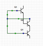
Can you draw a partial diagram to show the transistors that aren't on the diagram and the components that they're connected to?
Can you draw a partial diagram to show the transistors that aren't on the diagram and the components that they're connected to?
I just wanted to offer an update here. I have resorted to probably the most difficult way of diagnosing this, haha! I have been desoldering components down the line on the pos rail side. So far 20ish components seem ok.
Well, looks like I popped something during testing. Now I have no rail voltage on either side at all. Back to the drawing table.
nope. no waveform and 4mV when powered up and drops to zero when power is removed. The schematic also doesnt show a few zener diodes in it that are present on this board. Schematic seems to indicate only one, but there are three present here. I dont know if that has to do with the relay or not though. I did pull on PS transistor and bench test it and it checked out ok.
Start from the power terminals. Black probe on ground terminal. Confirm 12v on B+ anf remote as well as both sides of the inductor L801.
- Home
- General Interest
- Car Audio
- A/D/S power plate 80 and 100